Ordering from JLCPCB
Step-by-step instructions for ordering the dowjames v5.1 from JLCPCB with full SMT assembly.
Files
Download splitflapv5.1-pcb.zip from the custom-pcb/dowjames-v5.1/ folder of the repository and unzip it. Inside you'll find a splitflapv5.1-pcb/ folder with three files:
| File | Purpose |
|---|---|
gerber.zip |
Gerber + drill files — upload as the PCB manufacturing file |
bom.csv |
Bill of materials with LCSC part numbers |
positions.csv |
Pick-and-place / CPL file for component positioning |
Step 1: Upload Gerbers
Log in before uploading
Upload while logged in to your JLCPCB account. If you upload the gerber while logged out, the site may not auto-populate the PCB dimensions and you'll be left with blank X/Y fields.
- Unzip
splitflapv5.1-pcb.zip— the three files are inside thesplitflapv5.1-pcb/folder - Go to https://cart.jlcpcb.com/quote
- Click "Add gerber file" and upload
gerber.zip - JLCPCB will parse the files and show a PCB preview
Step 2: Configure PCB Options
| Setting | Value |
|---|---|
| Quantity | 10 (minimum for assembly — a good number for a display) |
| PCB Color | Your choice (black and green are popular) |
| PCB Thickness | 1.6mm — don't change this |
| Surface Finish | Default (HASL) is fine |
Leave everything else at defaults.
Step 3: Enable PCB Assembly
- Scroll down and toggle "PCB Assembly" to ON
- Select "Assemble top side"
- Set assembly quantity to match your PCB quantity
- Click "Confirm" or "Next"
Step 4: Upload BOM and Positions Files
- Click "Upload BOM/CPL"
- Upload
bom.csvas the BOM file - Upload
positions.csvas the CPL file - Click "Process BOM & CPL"
Step 5: Review Matched Parts
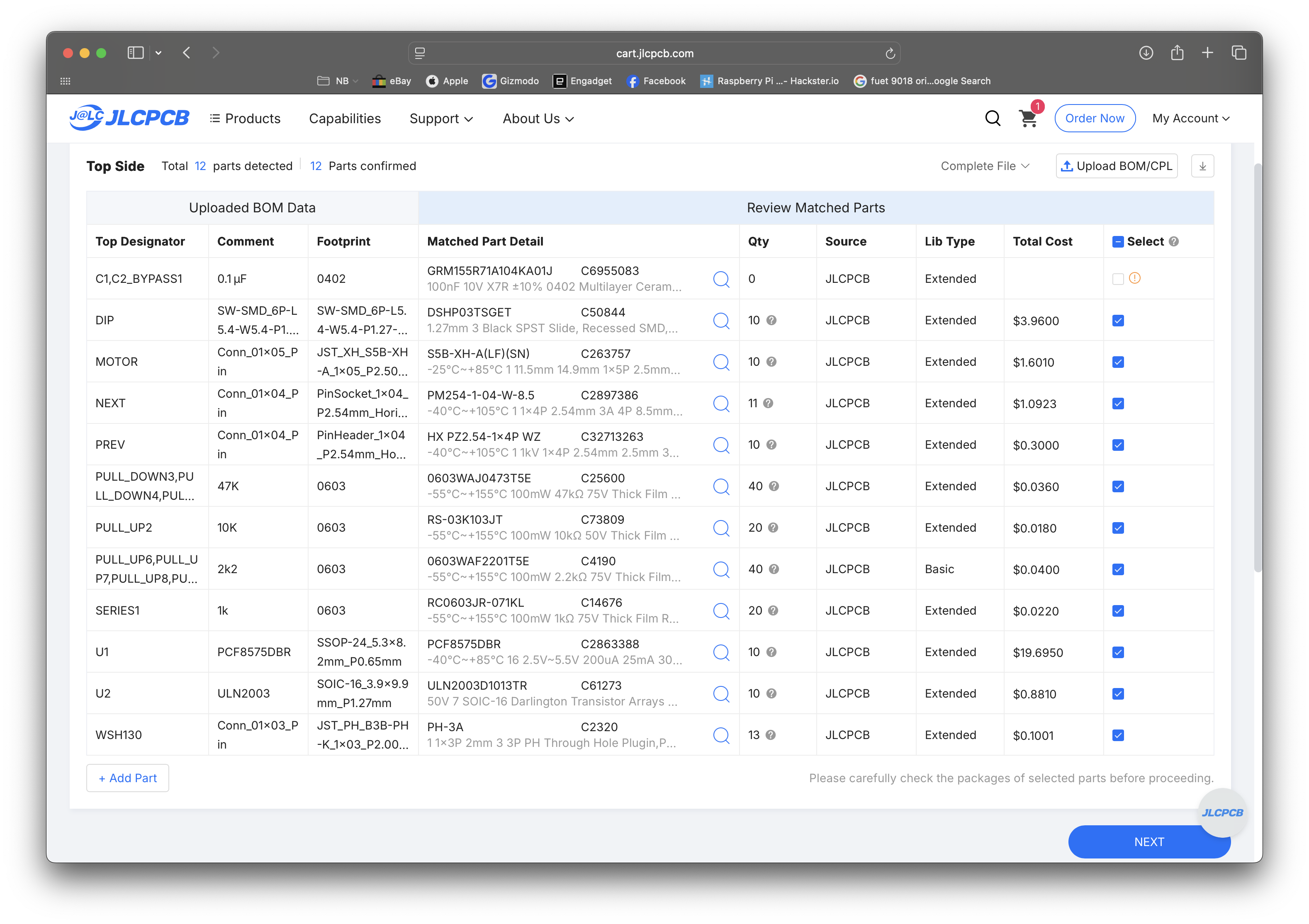
You should see 12 parts detected, 12 parts confirmed:
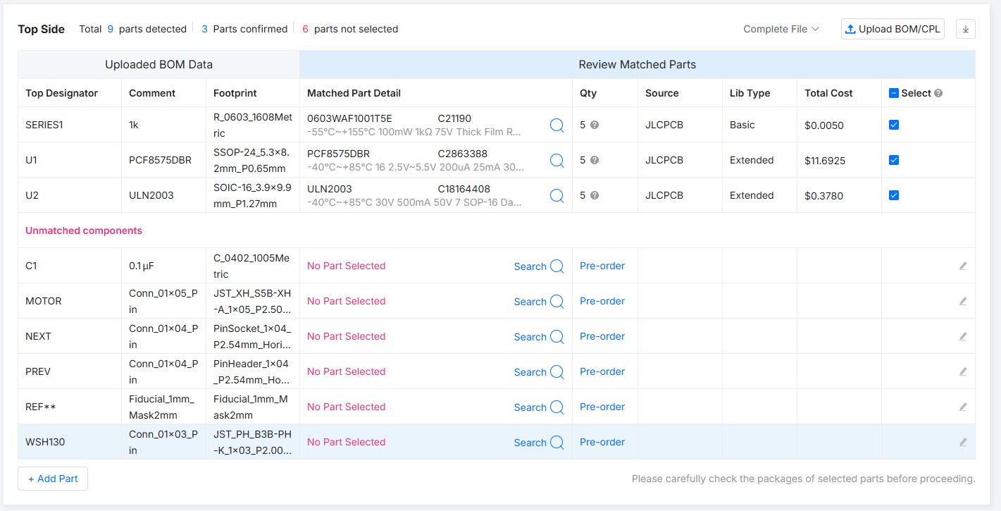
Only 3 parts matched?
If you see only 3 matched parts and many unmatched components, you uploaded the wrong files. Make sure you're using bom.csv and positions.csv from inside the splitflapv5.1-pcb/ folder within the zip — not any other folder.
Make sure all parts are selected. The two bypass capacitors — C1 and C2_BYPASS1 — may show quantity 0 and be unselected by default. Select them. Despite the BYPASS name they're capacitors, not resistors.
Step 6: Review Component Placement
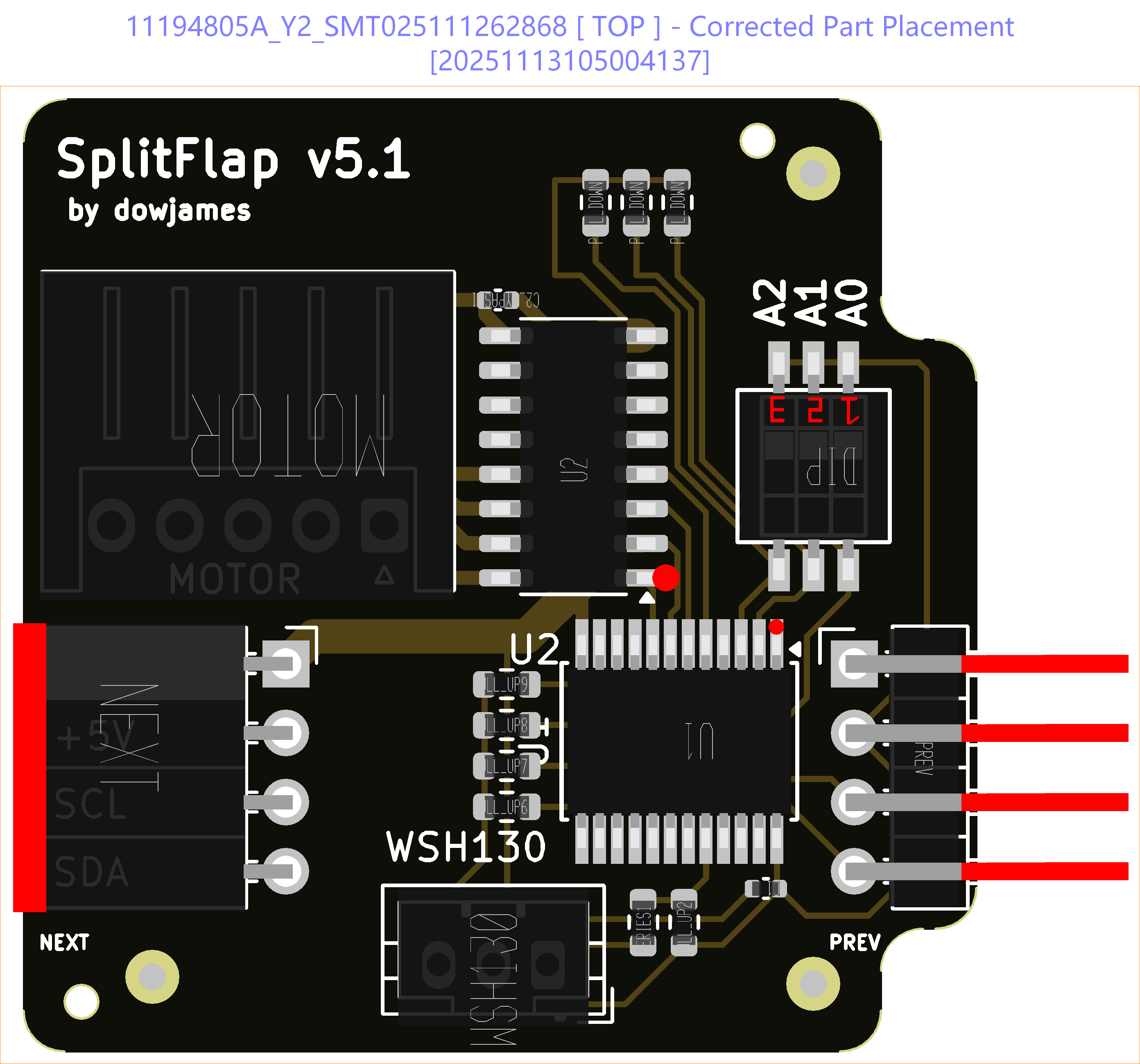
On the placement review page JLCPCB shows a 3D render of component positions. Some components may appear rotated — this is a known issue with their visualizer.
- Compare each component to the PCB silkscreen
- Rotate any components that appear sideways using the Rotate button
- The WSH130 hall sensor connector may need rotation
- The DIP switch will look "upside-down" — this is intentional. dowjames mounted it this way so the
1, 2, 3labels read correctly when installed. Don't try to fix it.
"I think they get confused because I mounted the dip switches upside down.. but because they're labelled 1,2,3 it would look stupid if they were mounted the other way round" — dowjames
Step 7: Review Pricing and Checkout
- Review the order summary
- Change the shipping method — JLCPCB defaults to the fastest (most expensive) option. Pick something more economical if you're not in a rush.
- Check the JLCPCB coupons page before placing your order.

Price reference as of Nov 2025 — 10 assembled PCBs shipped to Germany
Confirmation Emails from JLCPCB
JLCPCB may email you within a few hours with questions about component placement. This is normal for SMT orders.
"Are the polarities and placements correct?"
Reply: Yes, the placement and polarities are correct.
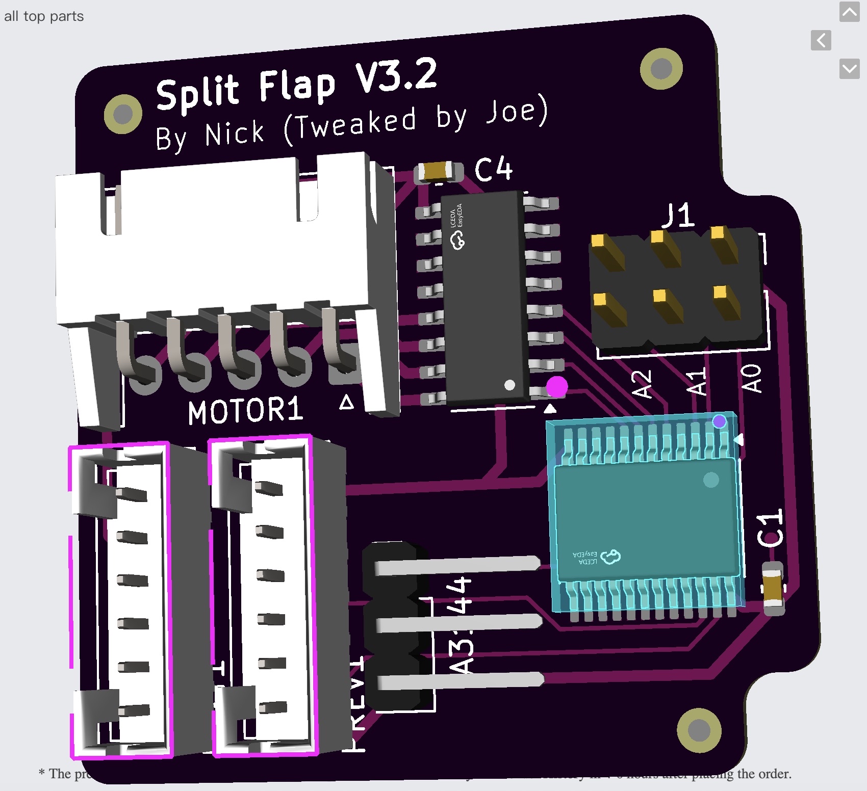
"Do you want the header pins at a right angle?"
Reply: Yes, that is correct. The right-angle headers are how the boards daisy-chain together.
Quick Reference
| Item | Value |
|---|---|
| Gerber file | gerber.zip |
| BOM file | bom.csv |
| CPL file | positions.csv |
| PCB quantity | 10 (minimum for assembly) |
| PCB thickness | 1.6mm |
| Assembly side | Top |
| Polarity email | Reply "Yes, correct" |
| Header pin email | Reply "Yes, right angle is correct" |