Dual Display
The dual display configuration drives up to 16 split-flap modules from a single ESP32 using two independent I²C buses. I used custom PCBs in my build, but the original DIY boards should work.
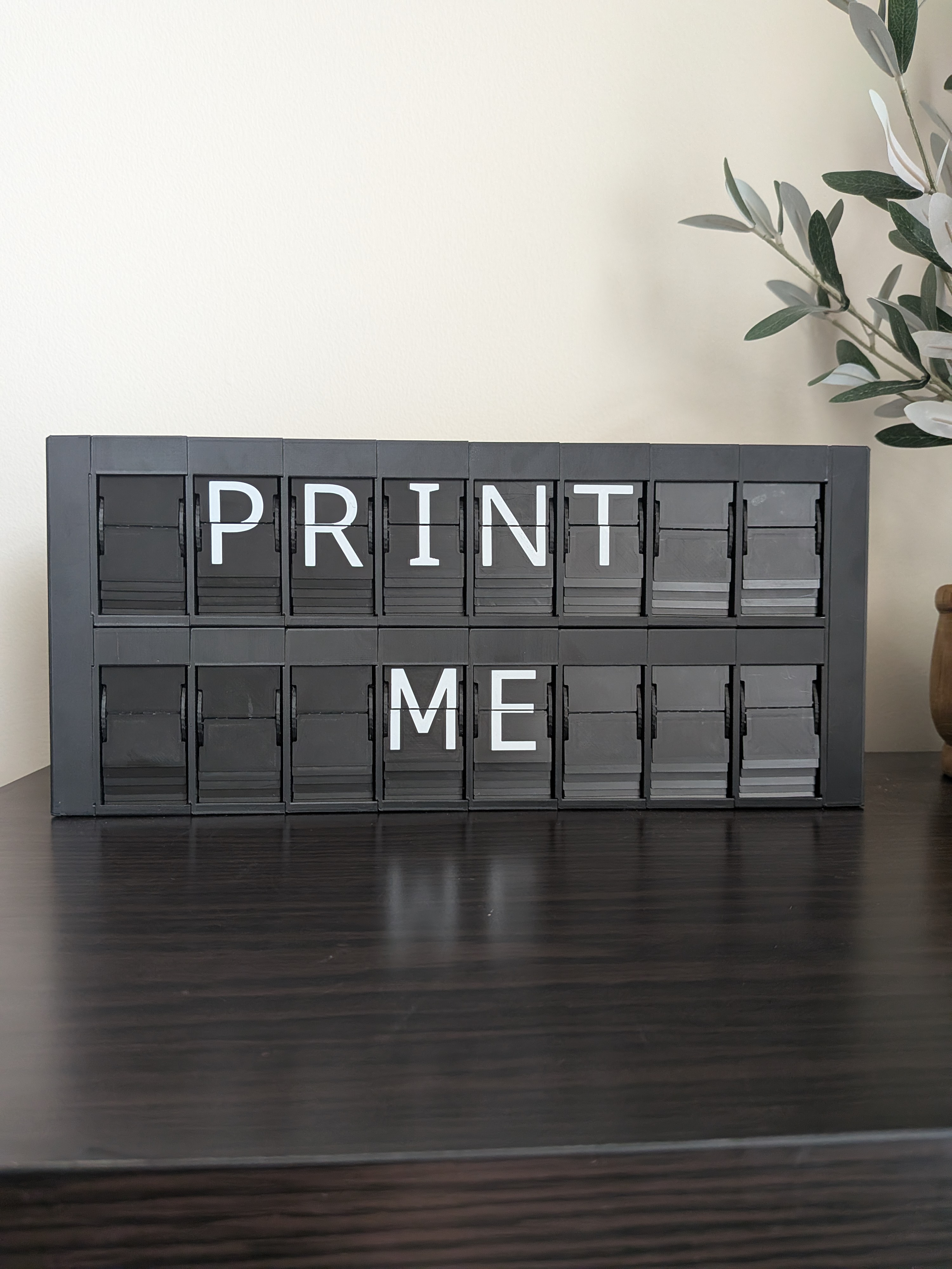
How it works
- Two I²C buses (Bus 1 + Bus 2), each driving one row of up to 8 modules
- Modules daisy-chain via 4-pin NEXT/PREV headers — no extra wiring between boards
- Each module has a DIP switch to set its I²C address (8 unique addresses per bus)
- The web interface controls both rows as a single 16-character display
Before you start
This build involves more complexity than a single-row display. Before diving in, make a few decisions upfront — they affect what you buy and what you print.
1. Power supply — choose between an integrated PSU (mains wiring inside the enclosure) or an external barrel jack adapter. See the Power page for a full comparison. This is the most important decision to make first.
2. Module board — choose between a custom PCB or the original DIY board. Custom PCBs arrive mostly assembled from JLCPCB; DIY boards require more soldering.
3. Shelly (optional) — if you want smart home integration and power monitoring, decide now. It fits inside the PSU enclosure but adds wiring complexity. See the BOM for details.
Build order
Follow these in order — decisions made early affect parts and prints later.
- Power — read this first, it determines which parts you need
- Bill of Materials — order everything before you start building
- Printed Parts — print and prepare all enclosure parts
- Controller Board — assemble and flash the ESP32 controller
- Assembly — put everything together