Assembly
Disclaimer
These instructions are provided by a hobbyist for educational purposes only. Follow these steps at your own risk. Option A involves AC mains voltage — if you're not comfortable with that, use Option B or consult a qualified electrician. Full disclaimer →
Most of the build steps from the original guide still apply, so these steps won't go into detail for items already documented there. If something is missing, please open an issue and it'll get addressed.
I used a custom PCB module for my setup, so these instructions focus on details specific to those boards. The steps are easily adaptable to the original DIY module board — let me know if anything is unclear for that path.
1. Build Modules
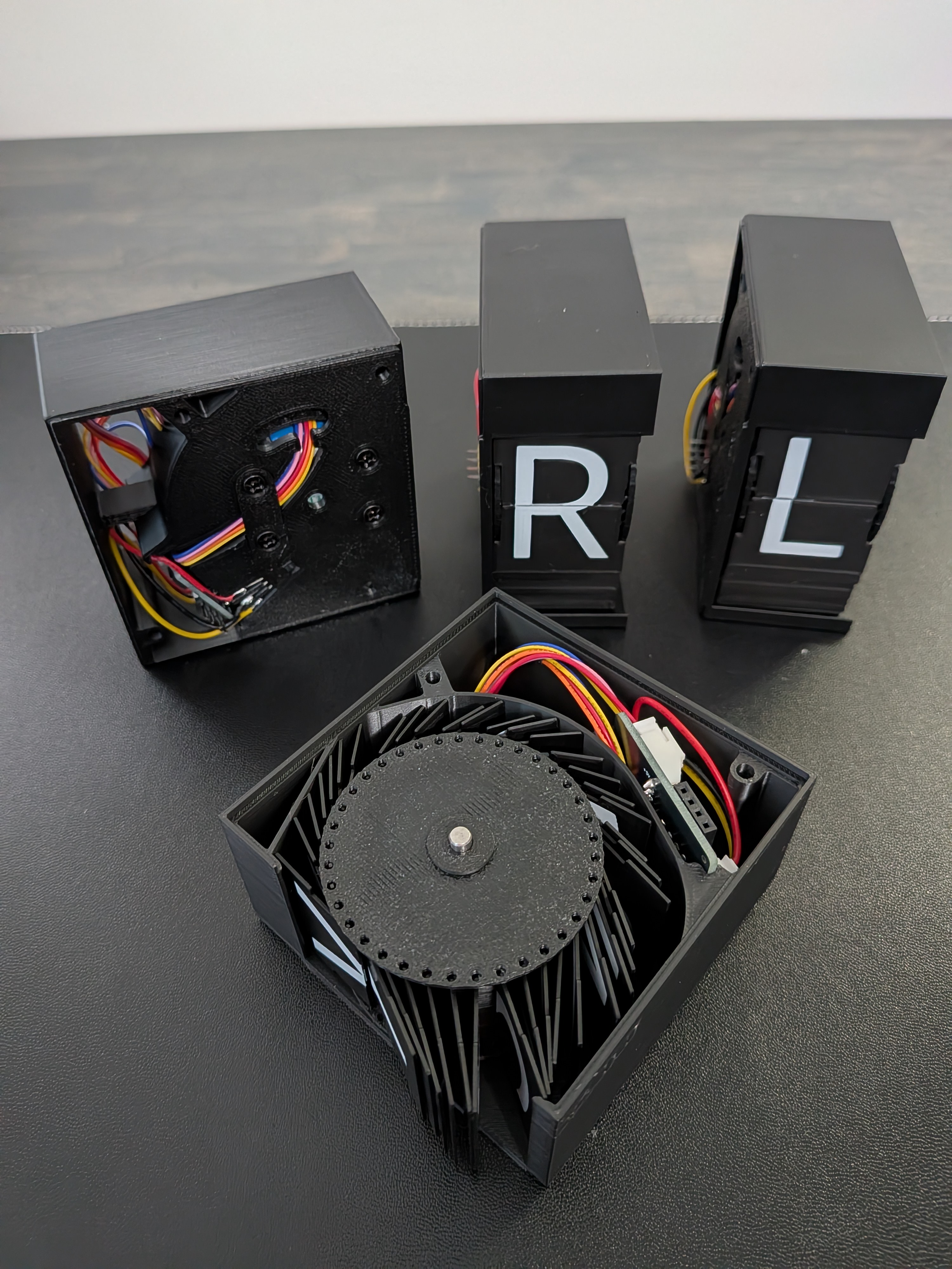
Building each module is essentially the same as the original design. This includes:
- Installing the motor and hall sensor in the enclosure
- Assembling the drum with flaps and magnet
- Connecting the DIY or custom PCB module board
2. Solder Module Wires
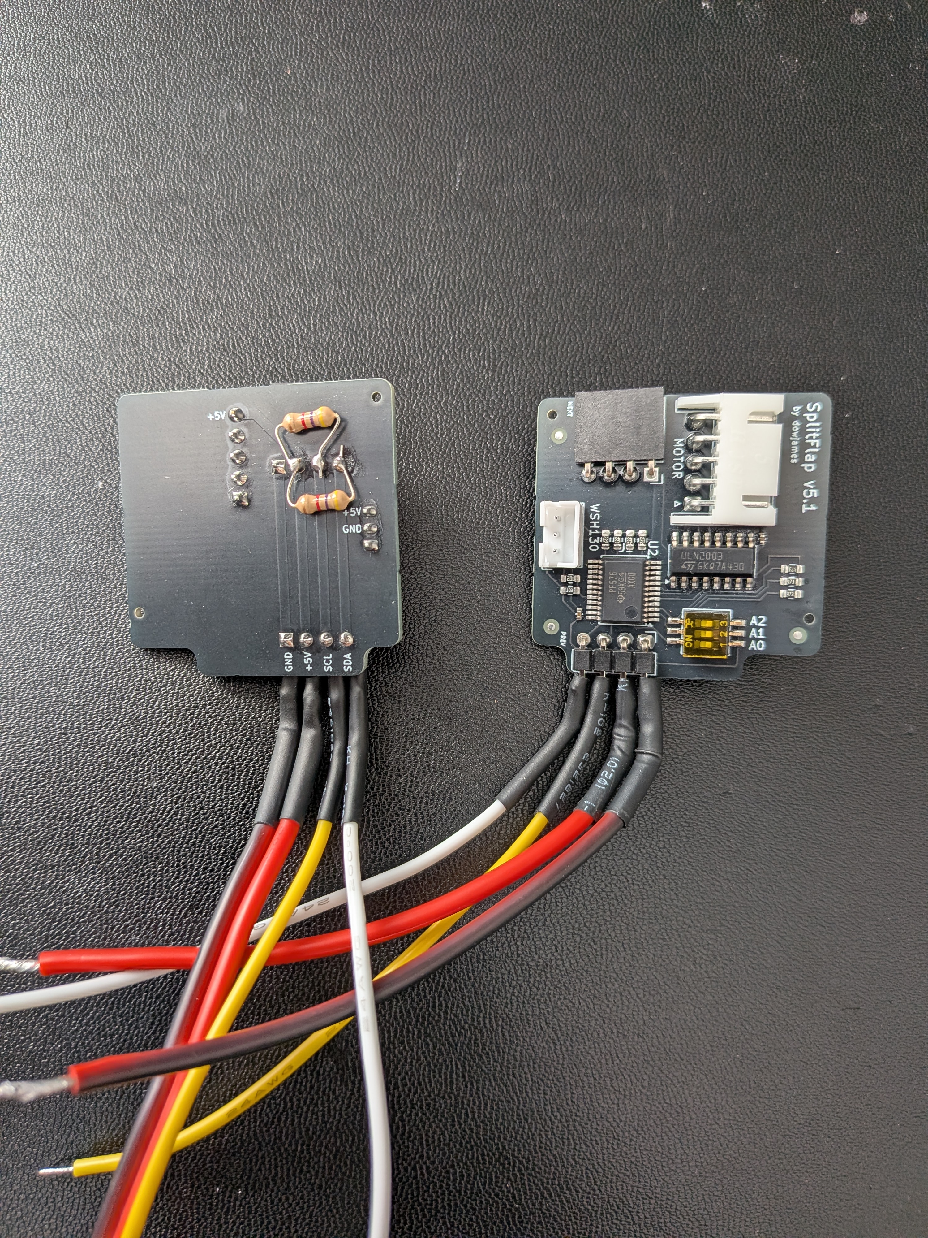
Regardless of the module board you're using, solder wires to the first module of each row (the one that will sit closest to the controller board) before connecting all modules together. Use 18 AWG wire for 5V/GND and 24 AWG wire for both I²C lines. Approximate wire lengths:
- Row 1 (top): 90mm
- Row 2 (bottom): 140mm
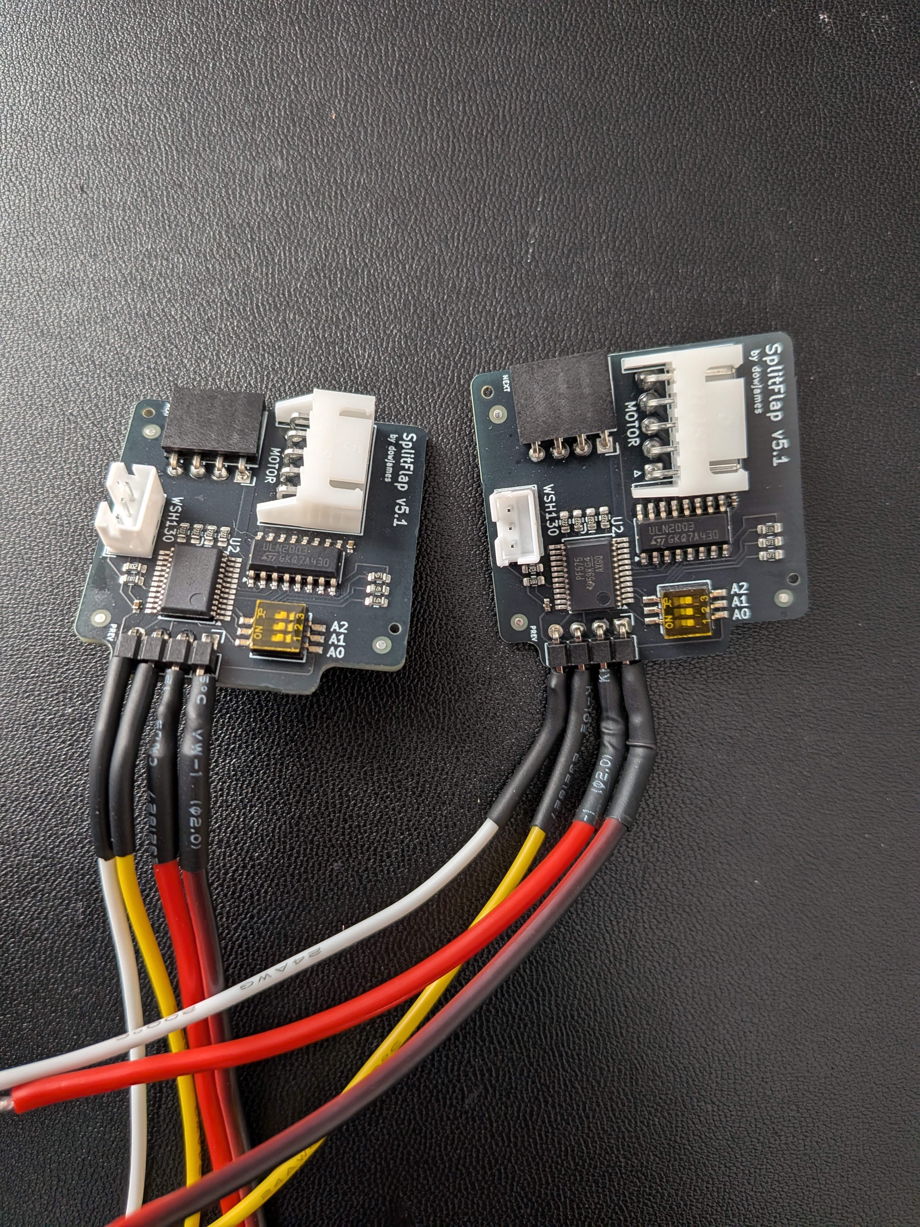
How I wired the first module
I used the custom PCB and soldered the wires directly to the PREV header pins, then added heat shrink tubing for protection. You'll also notice the pull-up resistors soldered on.
3. Prepare Threaded Rods
Cut all 8 threaded rods down to about 230mm (minimum 225mm). The cut doesn't have to be exact — there should be some extra room at both ends, between the rods and the end caps.
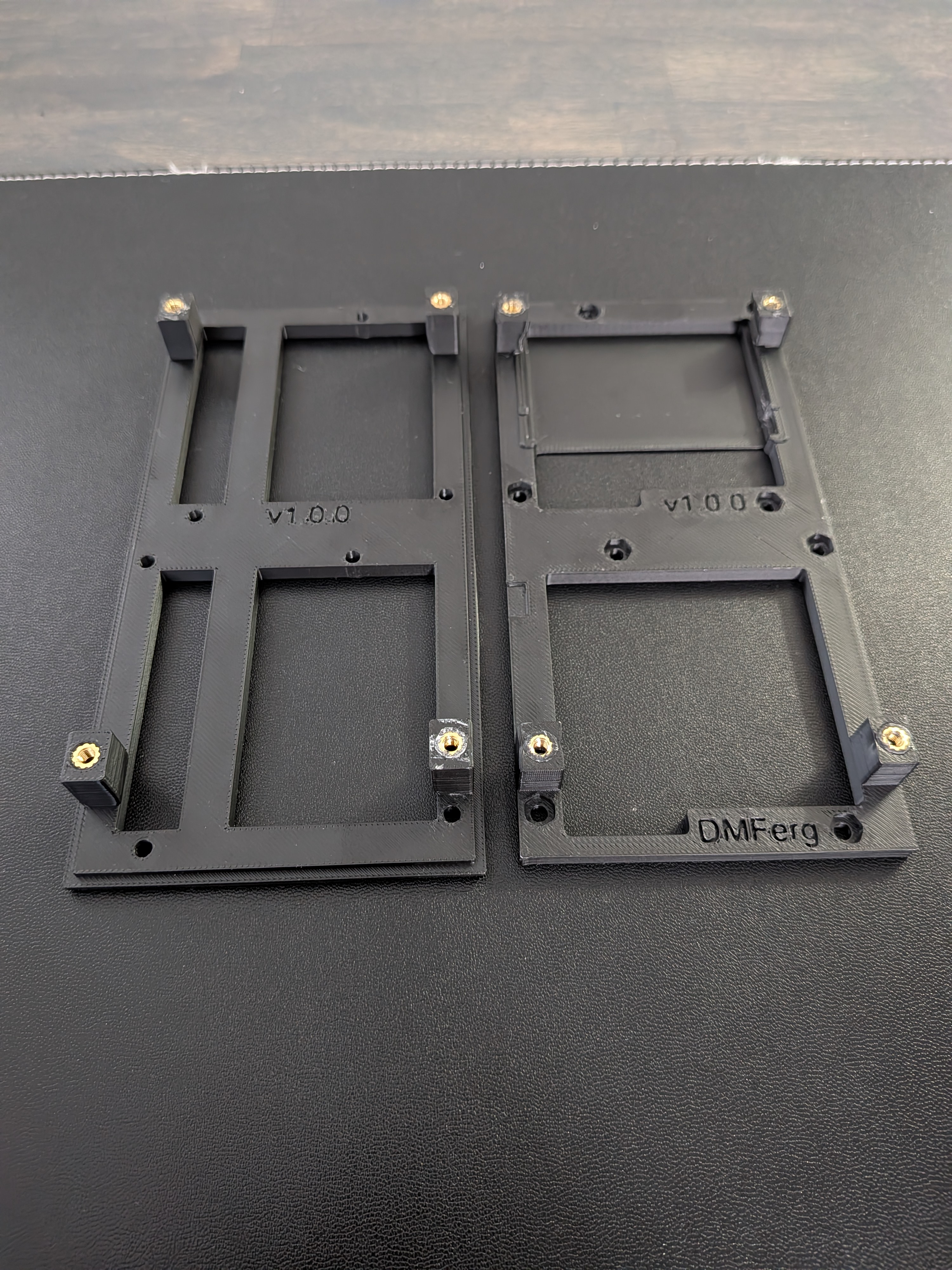
4. Install Heat Set Inserts
Use a soldering iron to install heat set inserts into the printed parts:
- Left end plate — 4× M3 × 4 × 5 heat set inserts
- Right end plate — 4× M3 × 4 × 5 heat set inserts
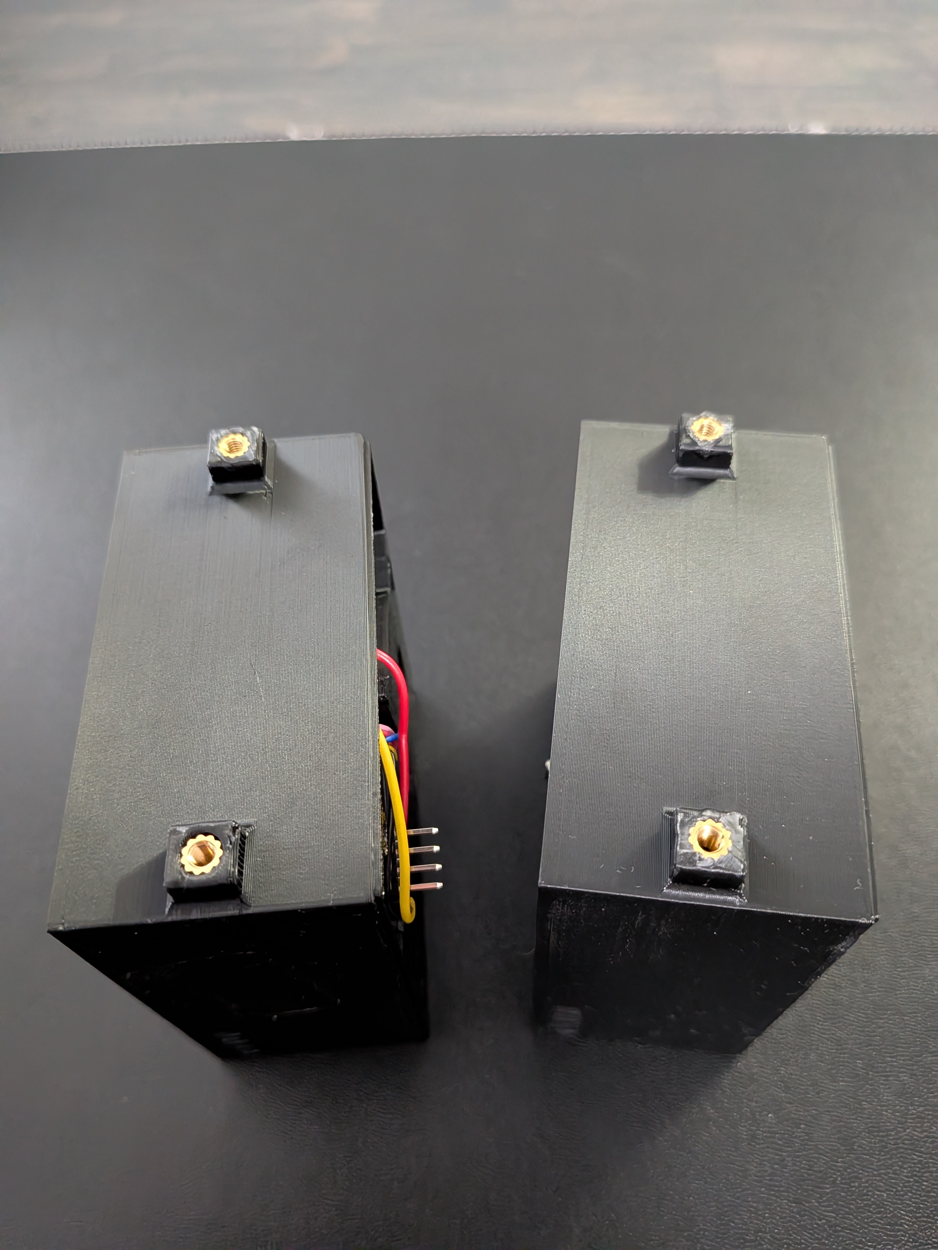
- D.1 SFD enclosure mounts (Option A only) — 4× M3 × 6 × 5 heat set inserts
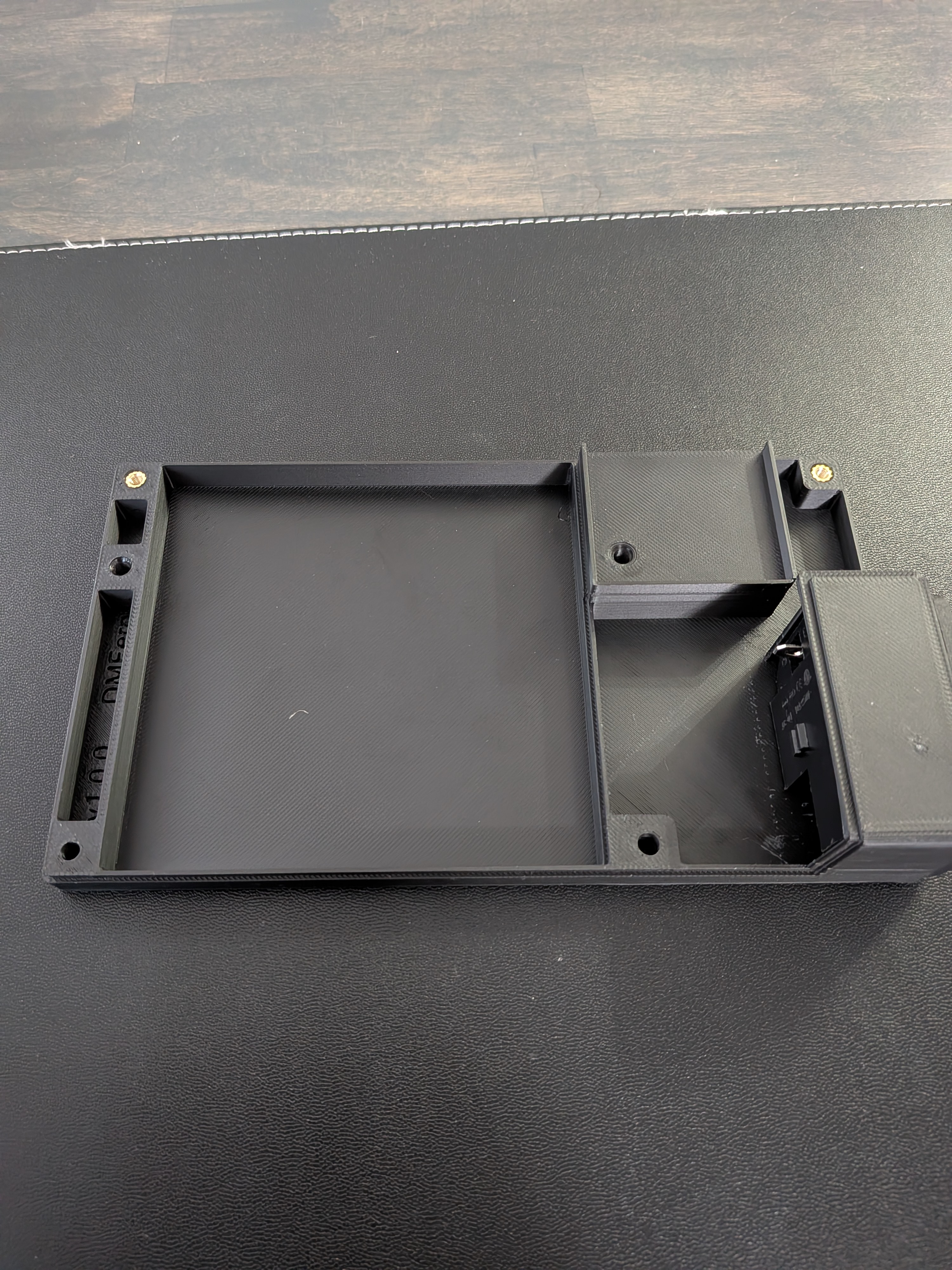
- PSU enclosure (Option A only) — 2× M3 × 4 × 5 heat set inserts
Watch for melted plastic
As you sink the inserts, make sure no melted plastic is pushed up around them. Any plastic protruding above the surface will prevent the end caps from sitting flush and leave gaps in the enclosure. Use a sharp knife to trim any excess.
5. Install Controller Board
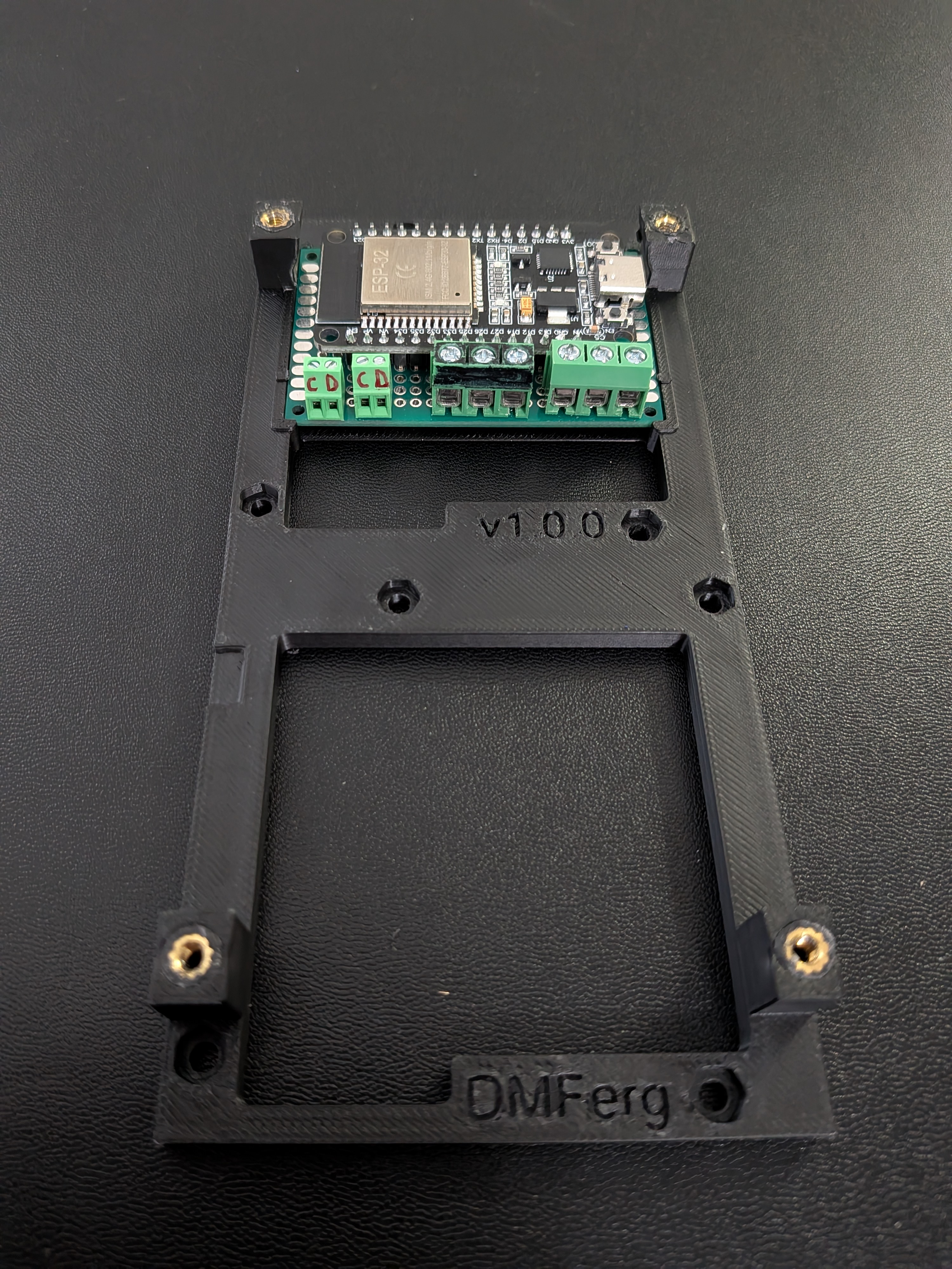
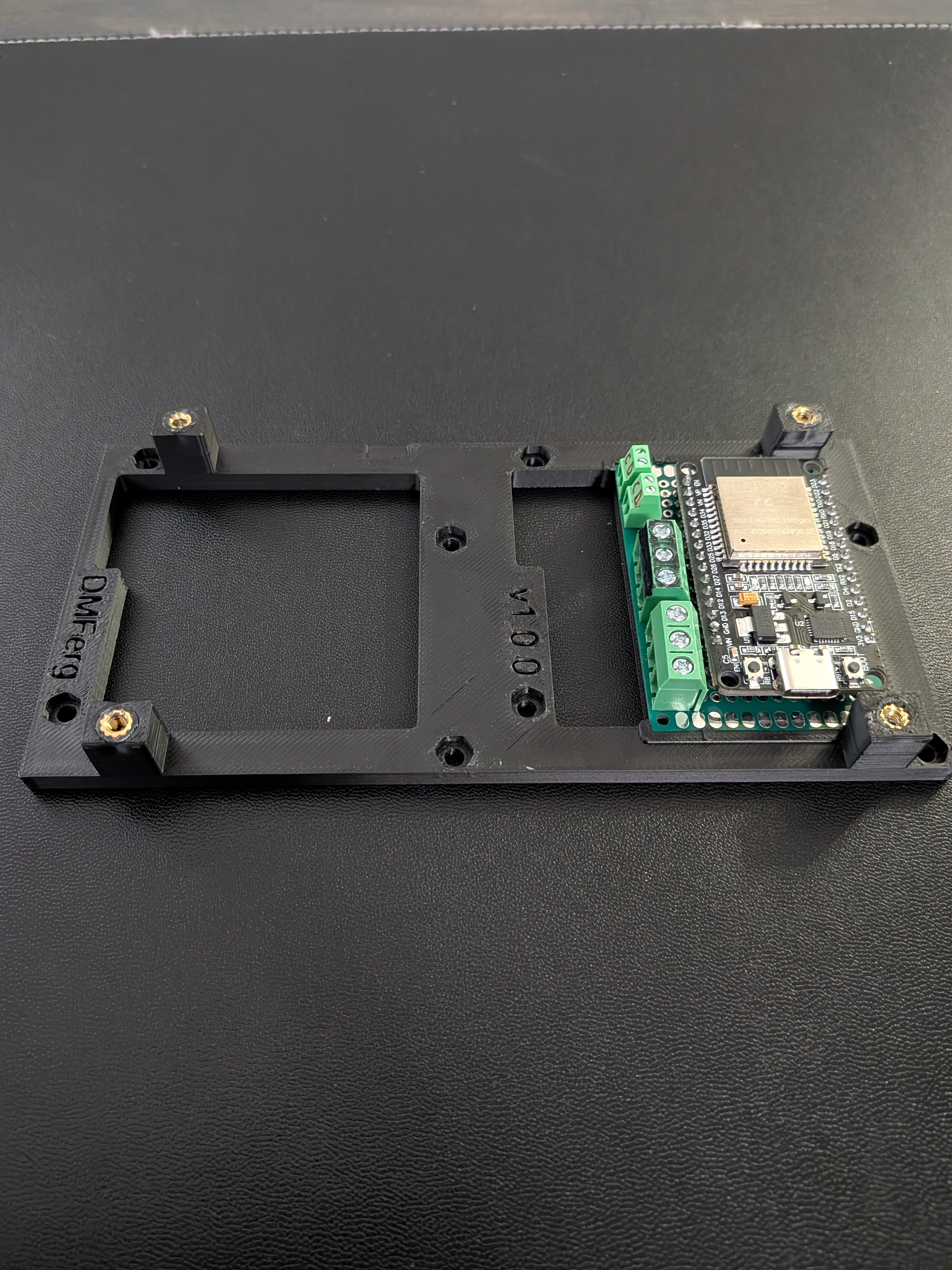
Place the controller board into the left end plate with the terminals facing down and the USB port facing forward. The fit should be snug — you may need to slightly flex the plate to slide the board in.
6. Connect Modules
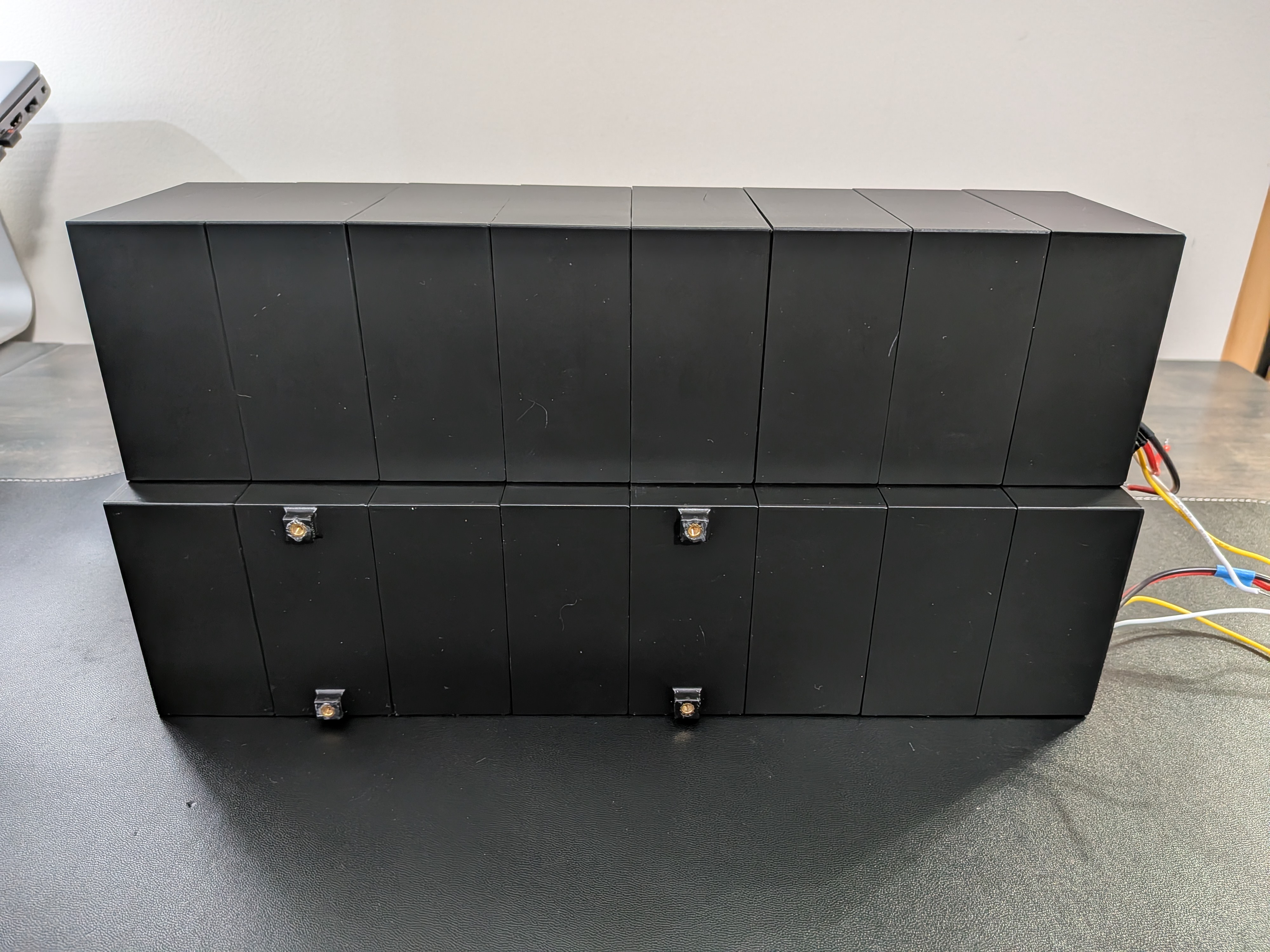
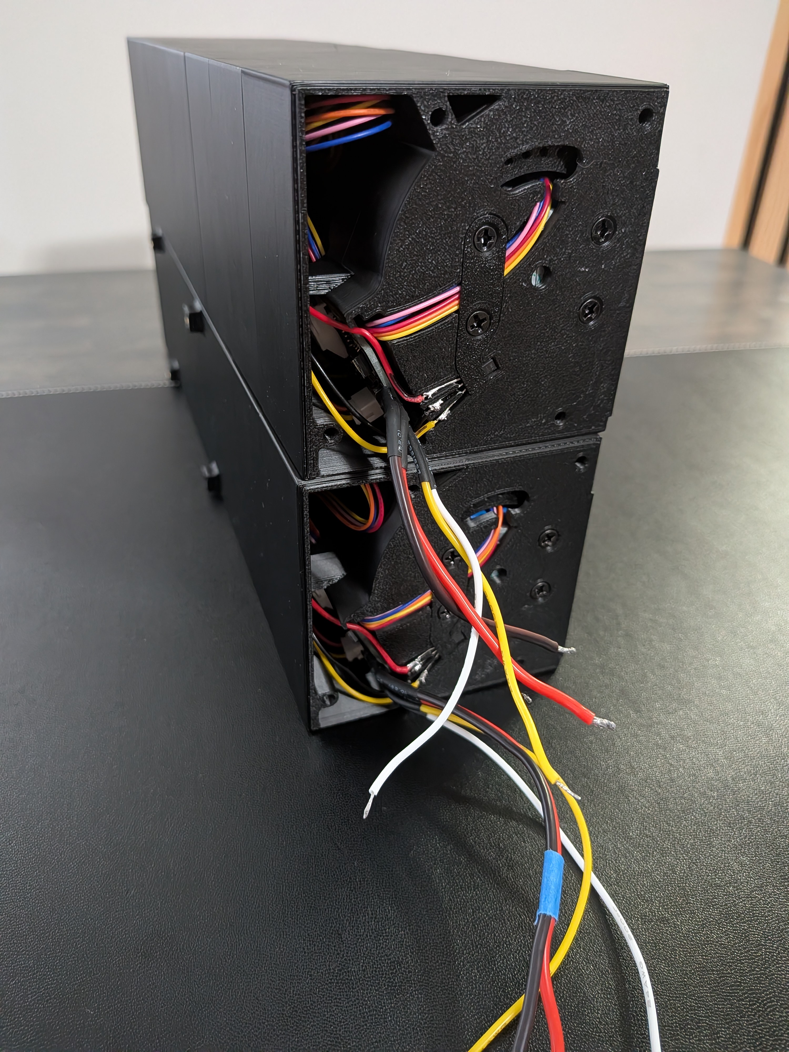
Connect all modules together in two rows of 8. Set the DIP switches on each module before connecting them — see the I²C address table for the correct address per position.
Tip
Painter's tape helps hold modules together while you assemble the row.
Custom PCB — stackable header required
If you're using the dowjames v5.1 custom PCB, you'll likely need a 2.54mm 4-pin stackable header to connect the PCBs. The PCBs are slightly narrower than the module enclosure by design, which makes connecting 8 consecutive boards directly difficult. Add this header between modules 4 & 5 or 5 & 6 on each row to take up the slack.
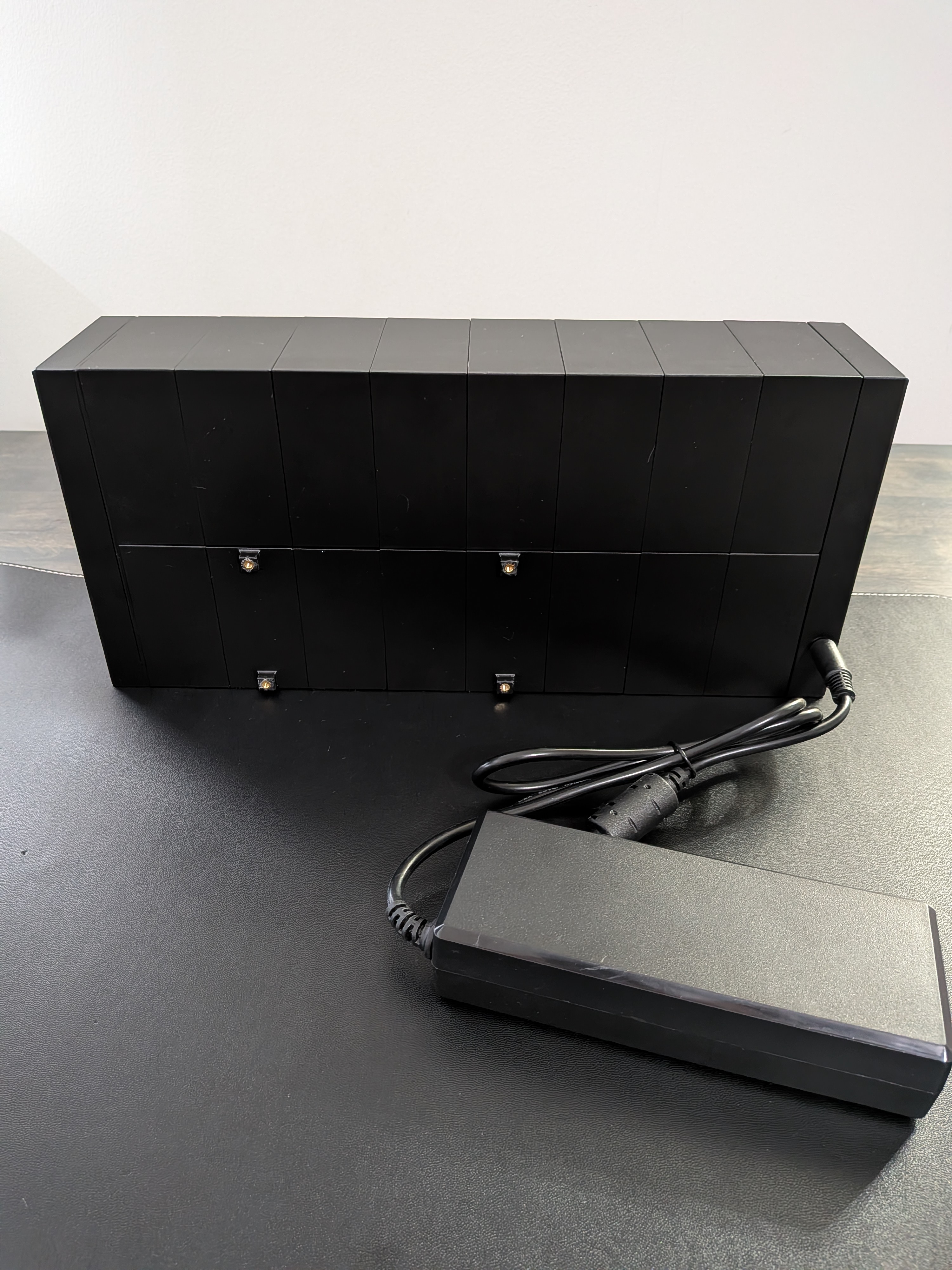
The diagram below shows how the 16 modules are arranged, viewed from the back. Numbering runs 8→1 left to right (mirrored from the front).
For Option A (Integrated PSU), modules 4 and 7 in Row 2 use the D.1 mount enclosure instead of the standard A.1 — these are the positions where the PSU enclosure attaches.
| ← Back view | 8 | 7 | 6 | 5 | 4 | 3 | 2 | 1 |
|---|---|---|---|---|---|---|---|---|
| Row 1 | A.1 | A.1 | A.1 | A.1 | A.1 | A.1 | A.1 | A.1 |
| Row 2 | A.1 | D.1 | A.1 | A.1 | D.1 | A.1 | A.1 | A.1 |
A.1 — Standard SFD Enclosure | D.1 — Mount Enclosure (Option A — Integrated PSU only)
7. Connect End Plates
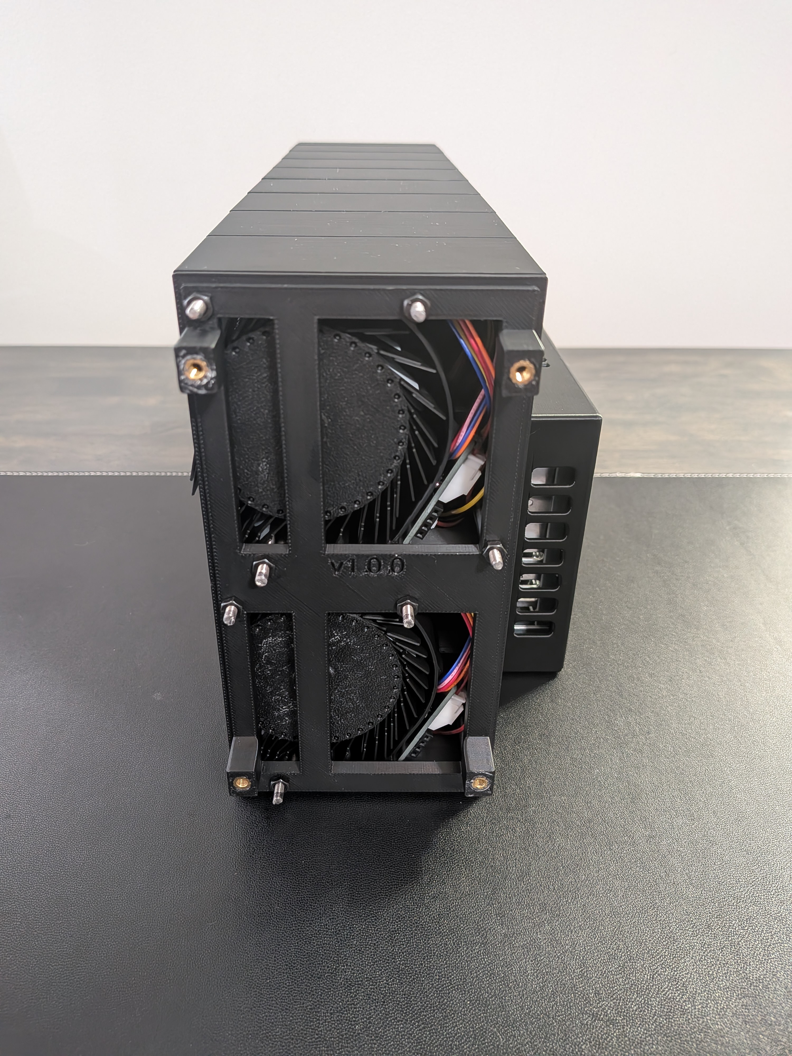
Connect the end plates to each side and insert the threaded rods into all 8 holes. Be careful not to push too hard on the lower front hole that slots through the flaps — you may hit a couple of flaps, but gently twisting the rod should let it pass. Finally, install 8 M3 nuts on each side. Hand-tighten enough to secure all modules, but not so much that the end modules get squeezed and the flap drums rub against the inside of the enclosure.
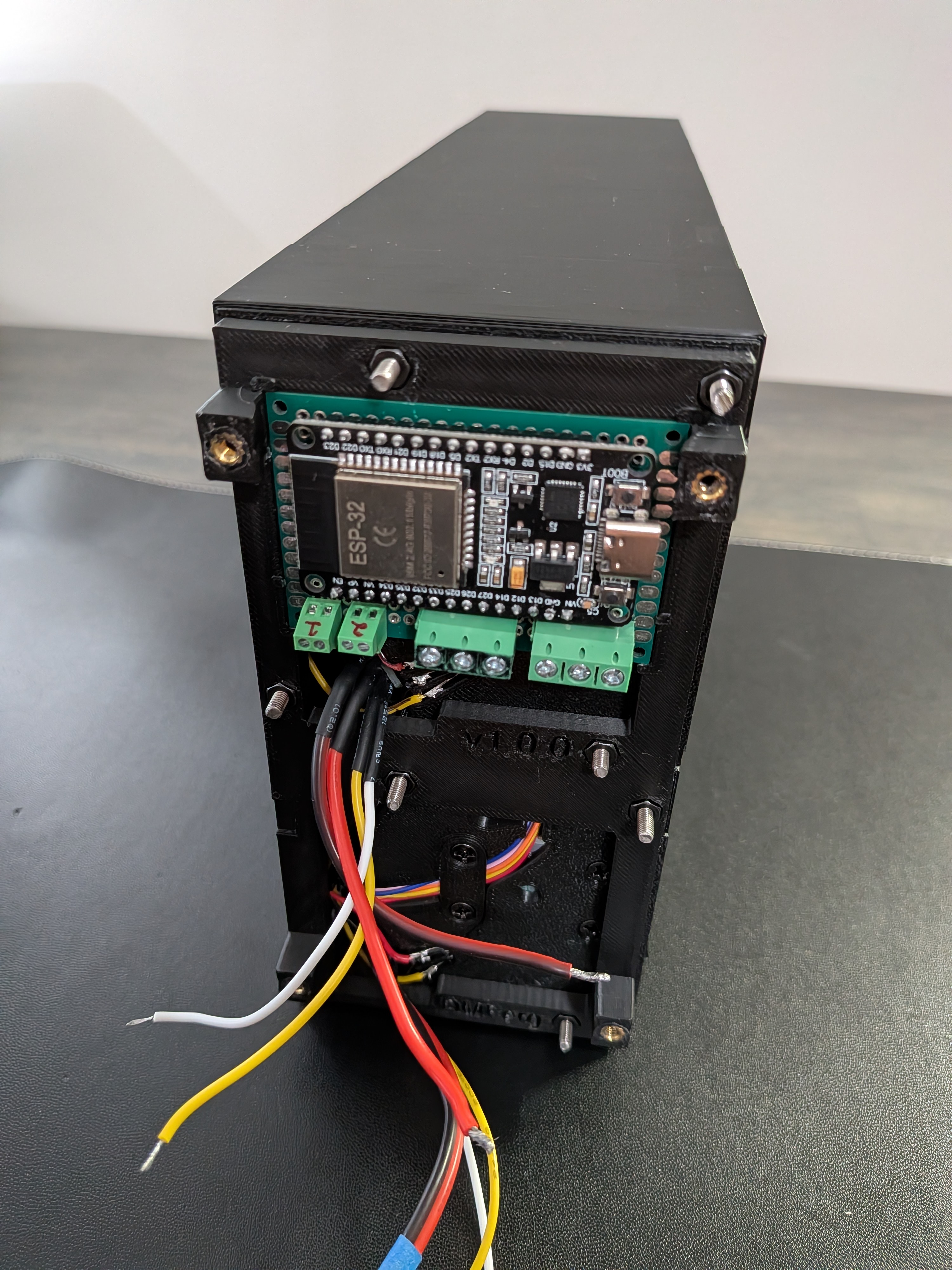
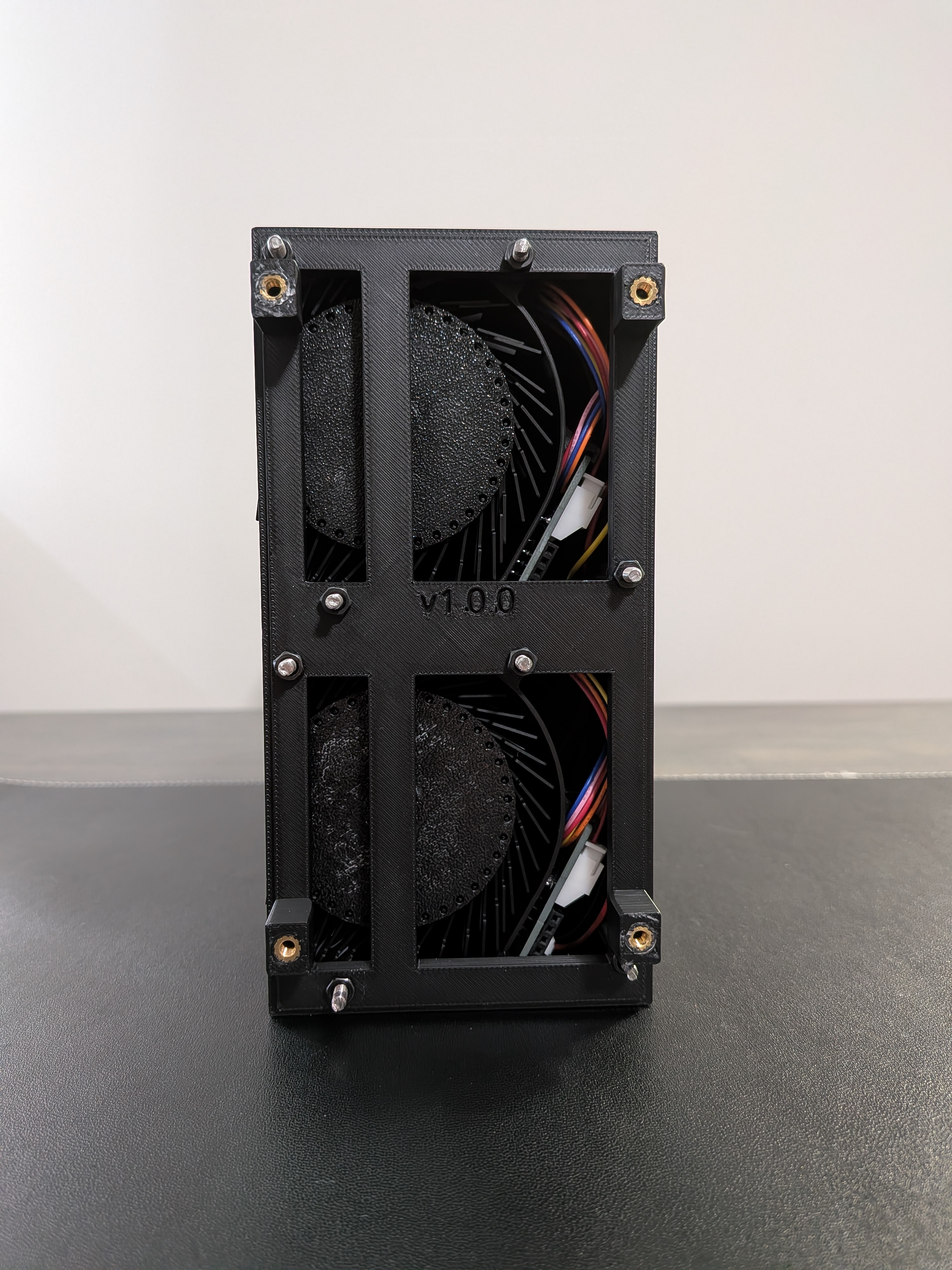
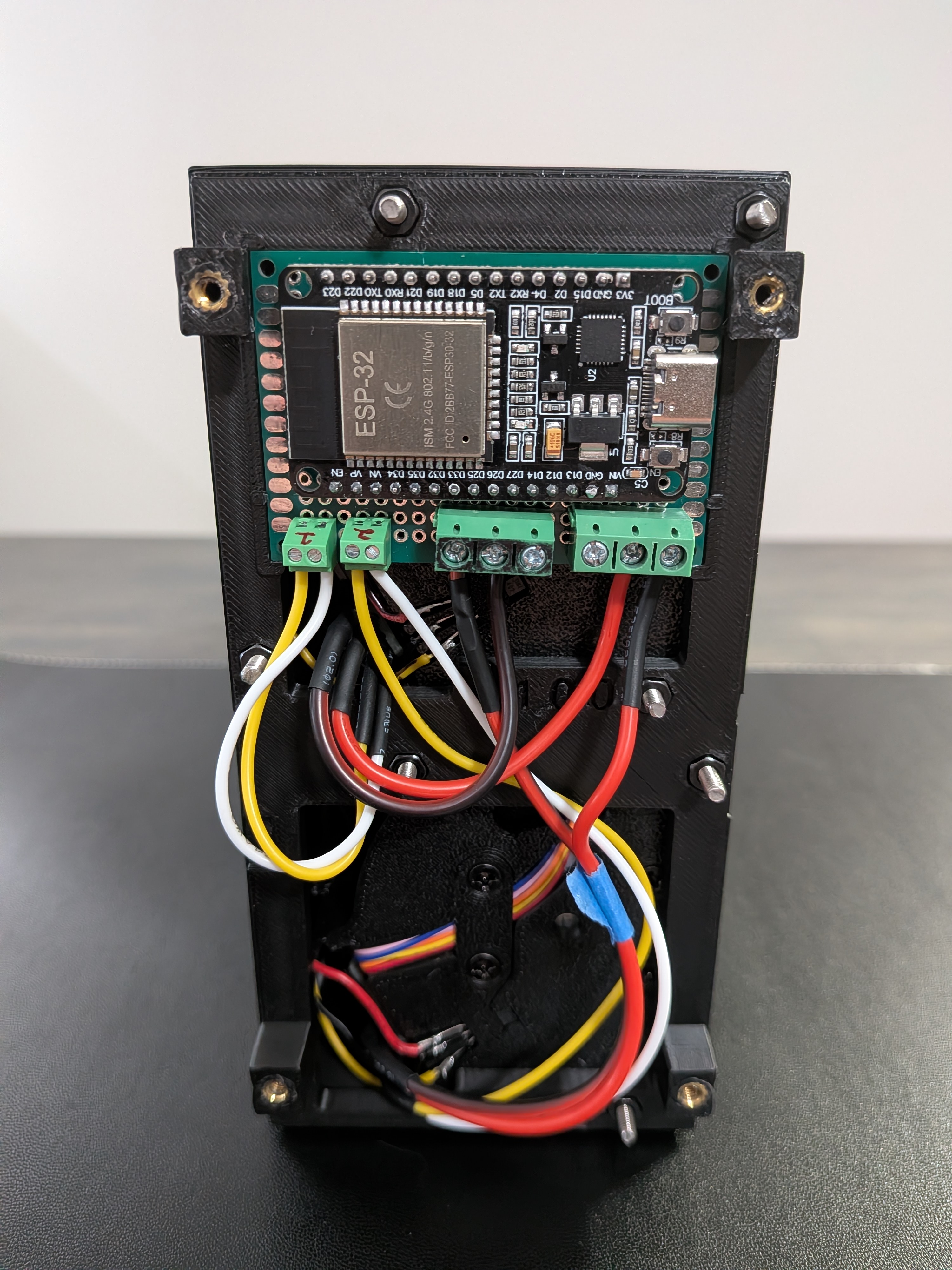
8. Wire Controller Board to Modules
The controller board provides two independent daisy-chain outputs:
- Bus 1 (GPIO 21/22 — left terminal) — drives the top row of up to 8 modules
- Bus 2 (GPIO 33/32 — right terminal) — drives the bottom row of up to 8 modules
The controller board's I²C outputs feed the first module of each row; from there, the NEXT/PREV headers on each PCB daisy-chain power and I²C through the rest of the row.
Connect the I²C wires you soldered in step 2 to the matching terminals on the controller board.
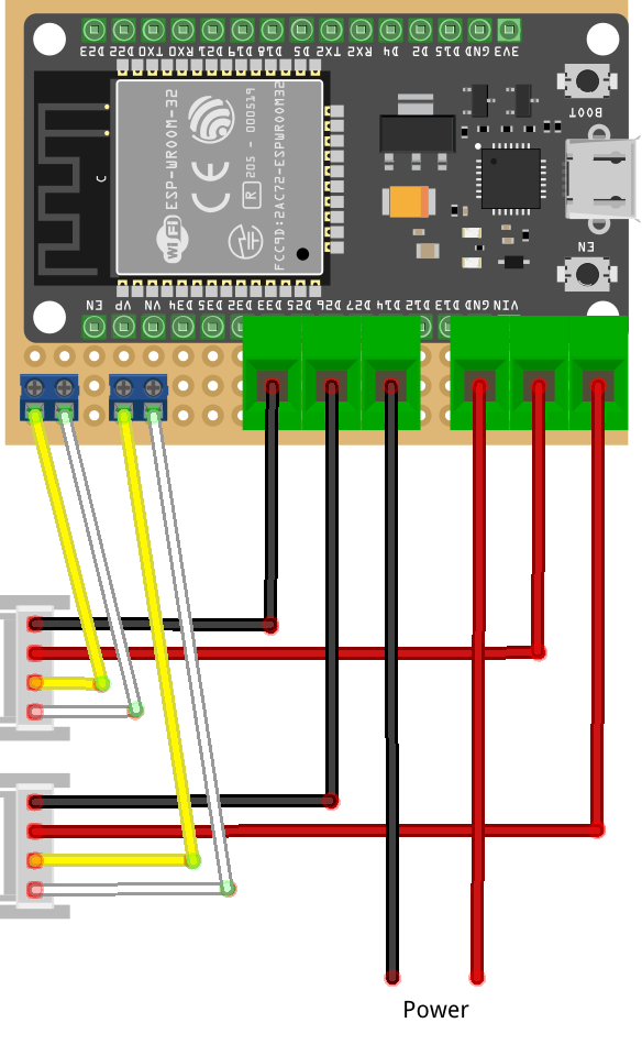
External wiring — 5V power input from the PSU on one side, Bus 1 and Bus 2 outputs to the split-flap daisy chains on the other
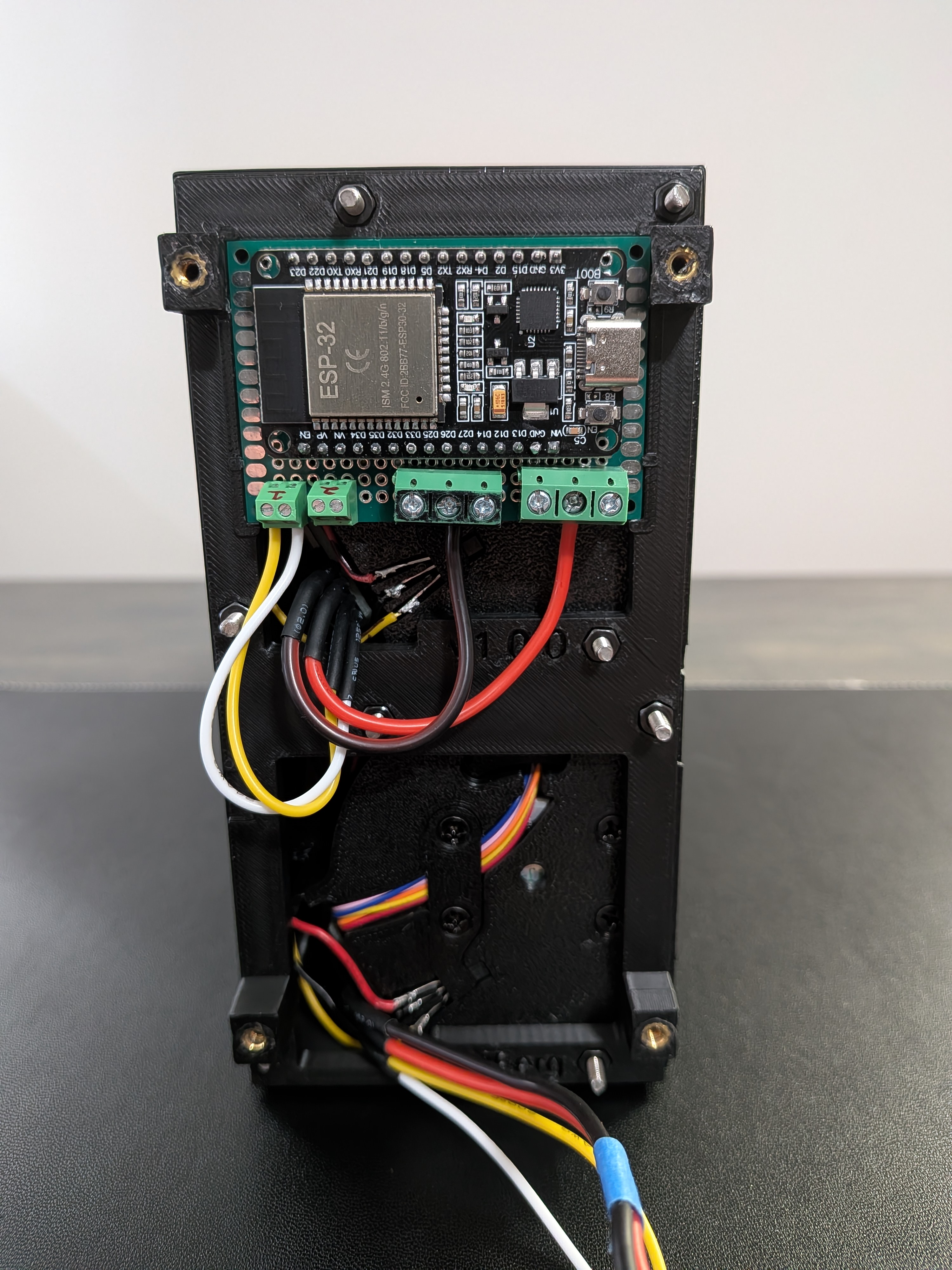
Test before closing the enclosure
This is a good time to flash the firmware (if you haven't already) and verify all 16 modules respond and home correctly. It's much easier to troubleshoot a misbehaving module now than after the enclosure is sealed.
The next steps depend on which power option you chose. Skip to the section that matches your build.
Mains voltage
These steps involve 120V AC wiring. If you're not comfortable working with mains voltage, get help from someone who is.
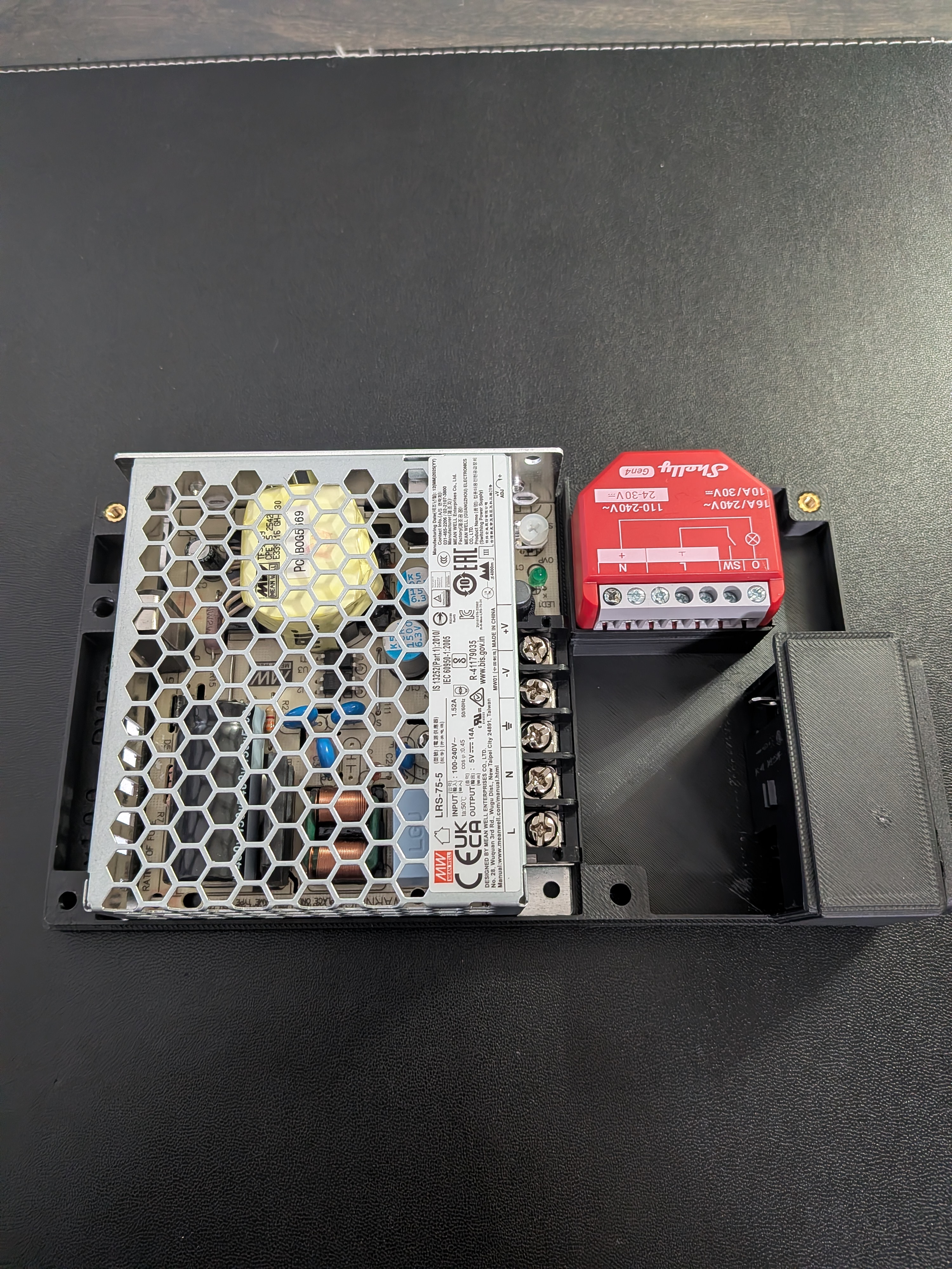
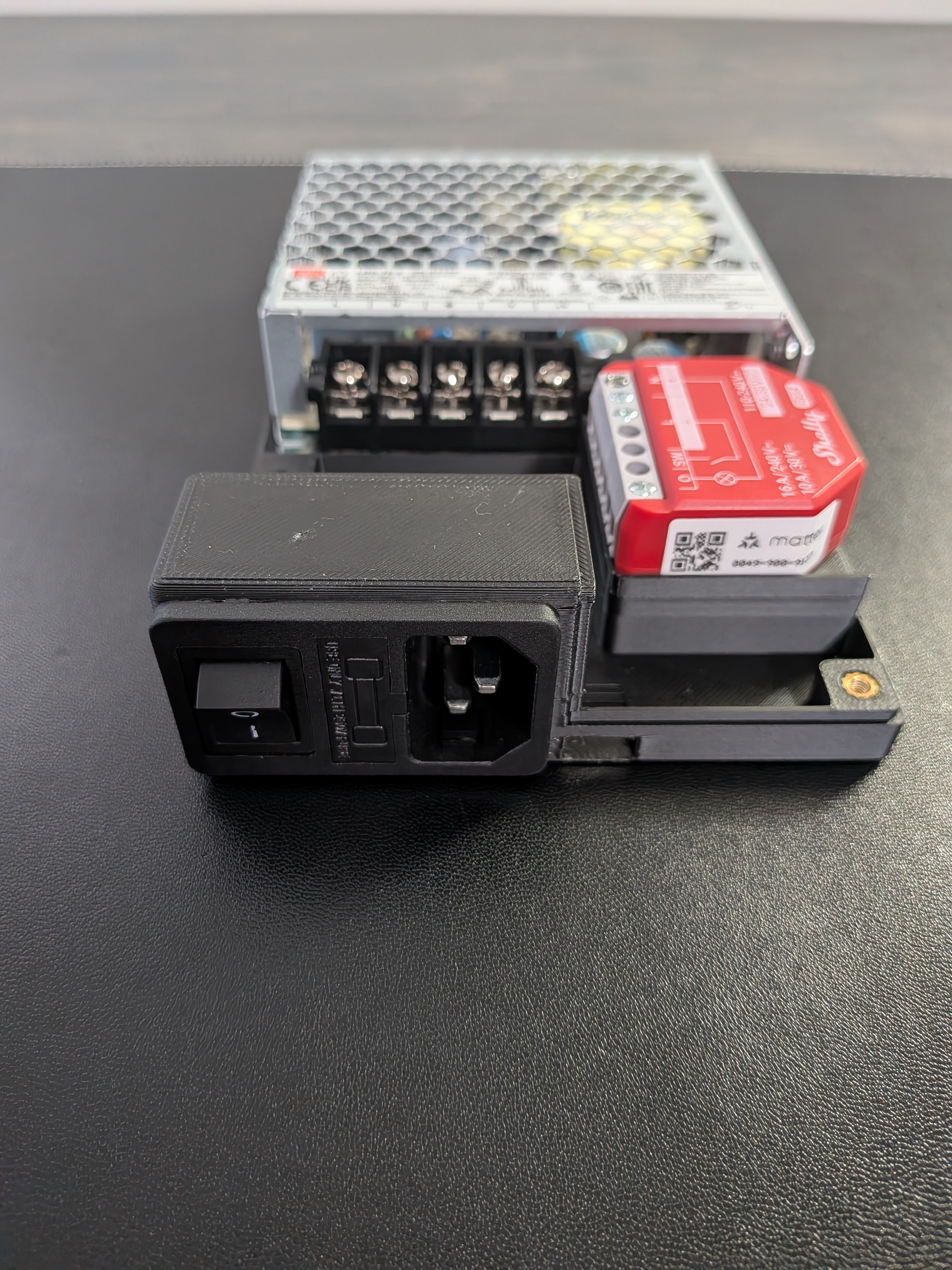
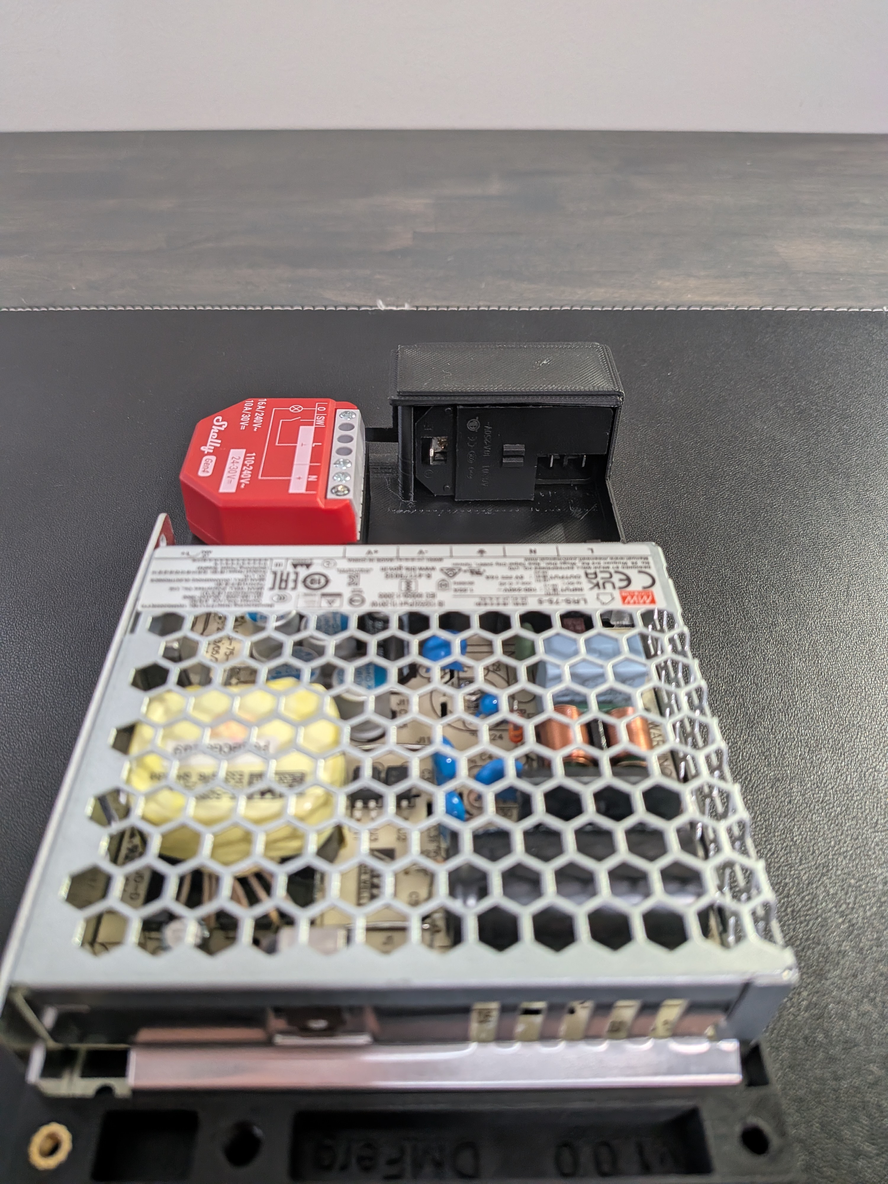
A.9. Install PSU Hardware
Dry-fit each piece of hardware in the PSU enclosure first to confirm everything seats correctly. You'll remove them again before wiring.
- Mount the LRS-75-5 into the PSU enclosure.
- (Optional) Install the Shelly 1PM Gen4 for smart power monitoring.
- Install the main power switch into its 3D-printed mount with the switch facing the bottom.
Switch is hard to remove once installed
Once pressed in, the switch is nearly impossible to remove without breaking the printed mount. Verify the mount has no imperfections and that you have the correct orientation before installing.
A.10. Prepare PSU Wires
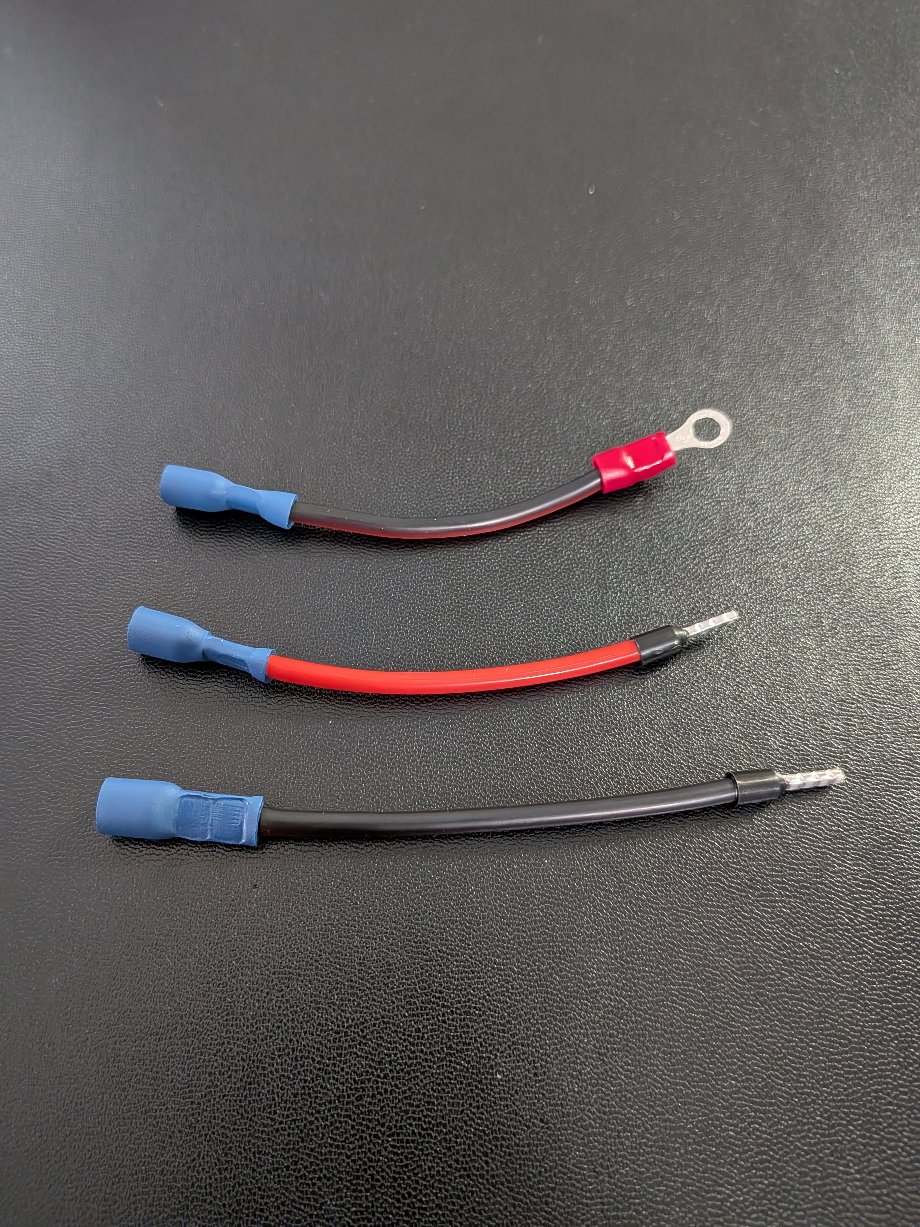
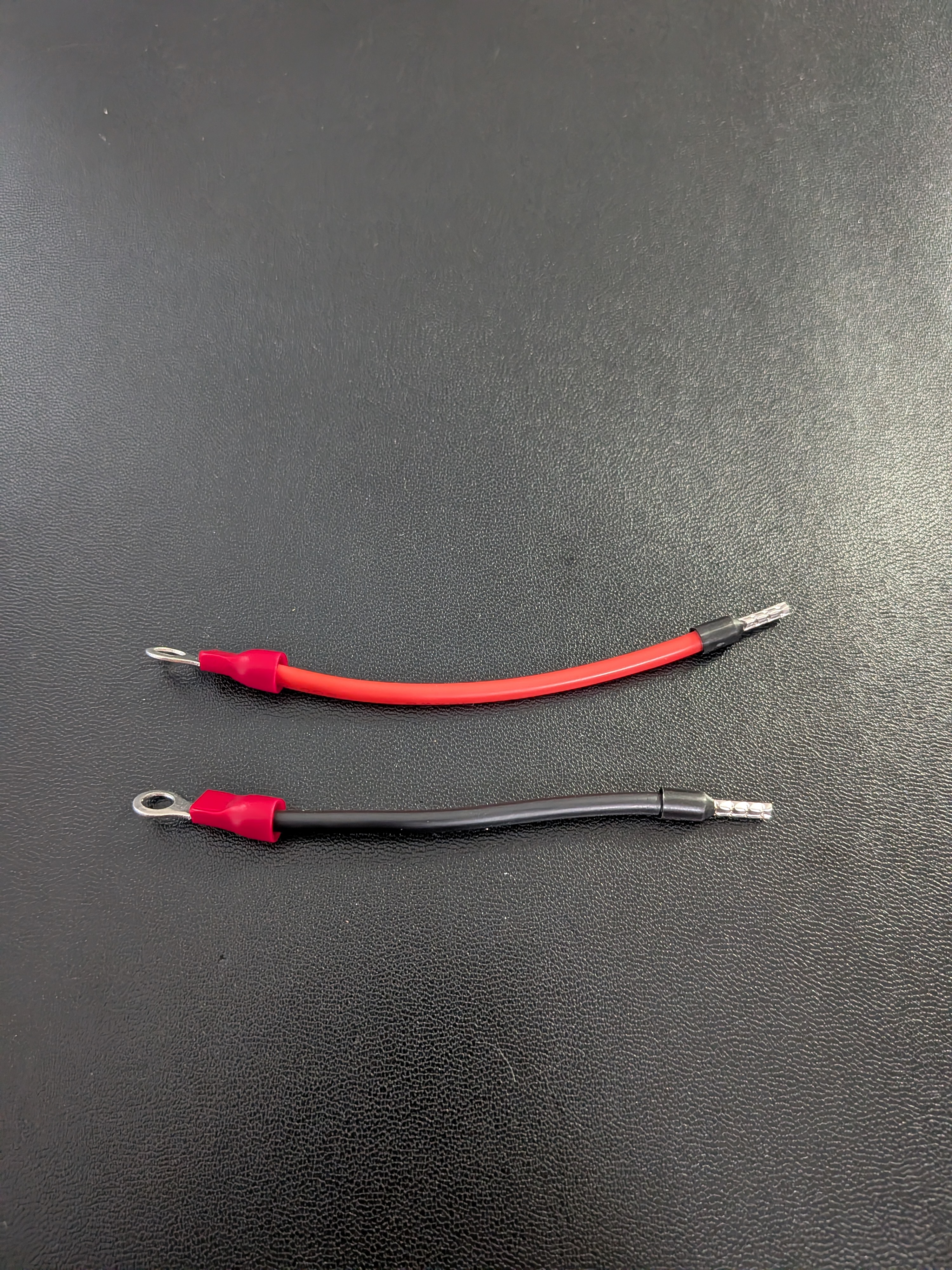
Use 16 AWG for 120V lines. Cut and terminate wires based on whether you installed the Shelly.
| Wire | From | To | Length | From Connector | To Connector |
|---|---|---|---|---|---|
| GND | Outlet (G) | PSU (G) | ~70mm | Female spade | M4 ring |
| LINE | Outlet (L) | Shelly (L) | ~80mm | Female spade | Wire ferrule |
| NEUTRAL | Outlet (N) | Shelly (N) | ~90mm | Female spade | Wire ferrule |
| LINE | Shelly (O) | PSU (L) | ~90mm | Wire ferrule | M4 ring |
| NEUTRAL | Shelly (N) | PSU (N) | ~80mm | Wire ferrule | M4 ring |
| Wire | From | To | Length | From Connector | To Connector |
|---|---|---|---|---|---|
| GND | Outlet (G) | PSU (G) | ~70mm | Female spade | M4 ring |
| LINE | Outlet (L) | PSU (L) | ~70mm | Female spade | M4 ring |
| NEUTRAL | Outlet (N) | PSU (N) | ~70mm | Female spade | M4 ring |
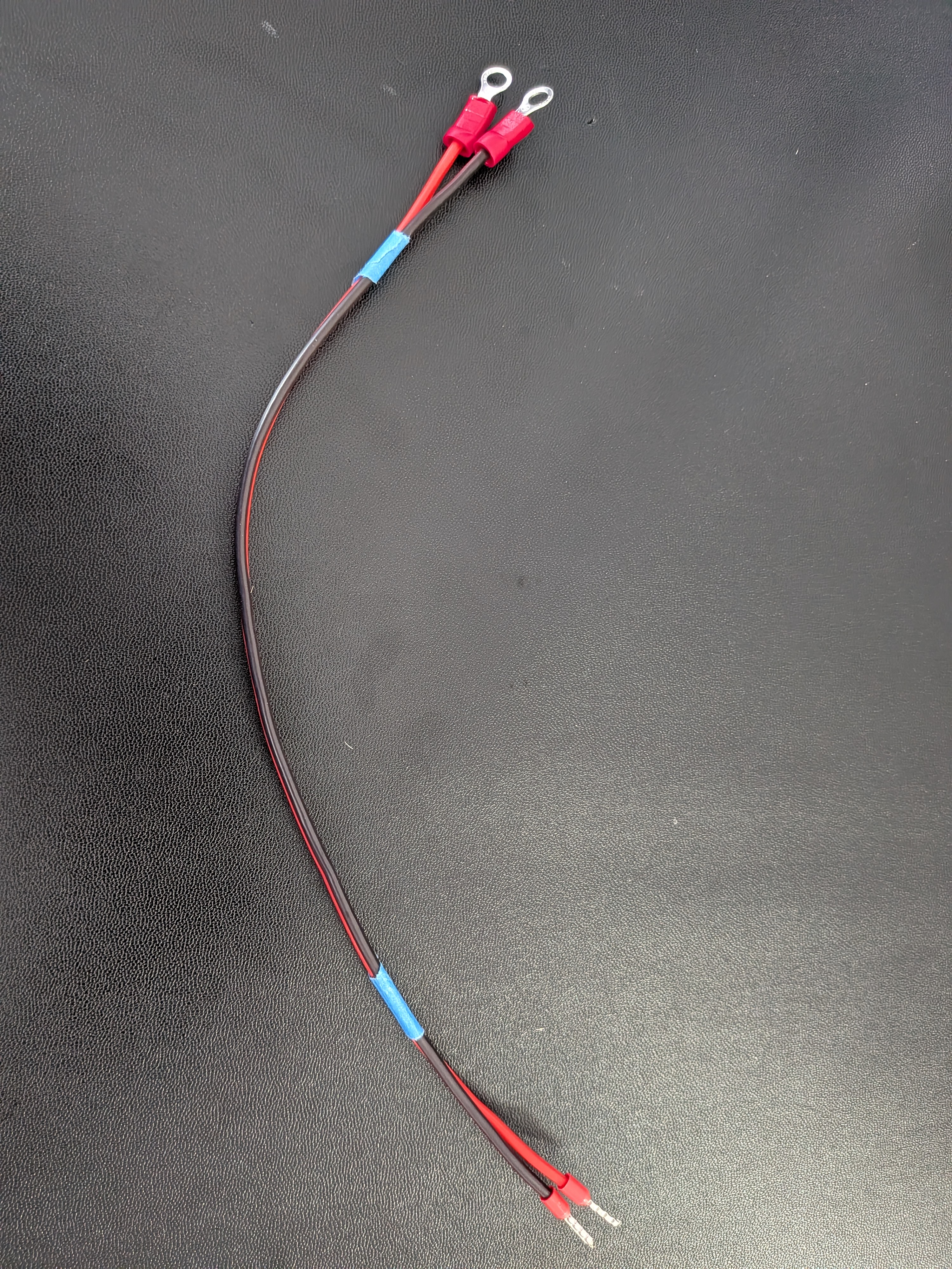
Use 18 AWG for the 5V DC lines from the PSU to the controller board. Keep the two wires paired — don't separate them.
| Wire | From | To | Length | From Connector | To Connector |
|---|---|---|---|---|---|
| 5V | PSU (V+) | Controller board (+5V terminal) | ~280mm | M4 ring | Wire ferrule |
| GND | PSU (V−) | Controller board (GND terminal) | ~280mm | M4 ring | Wire ferrule |
A.11. Wire the PSU
You can now connect all the power hardware together.
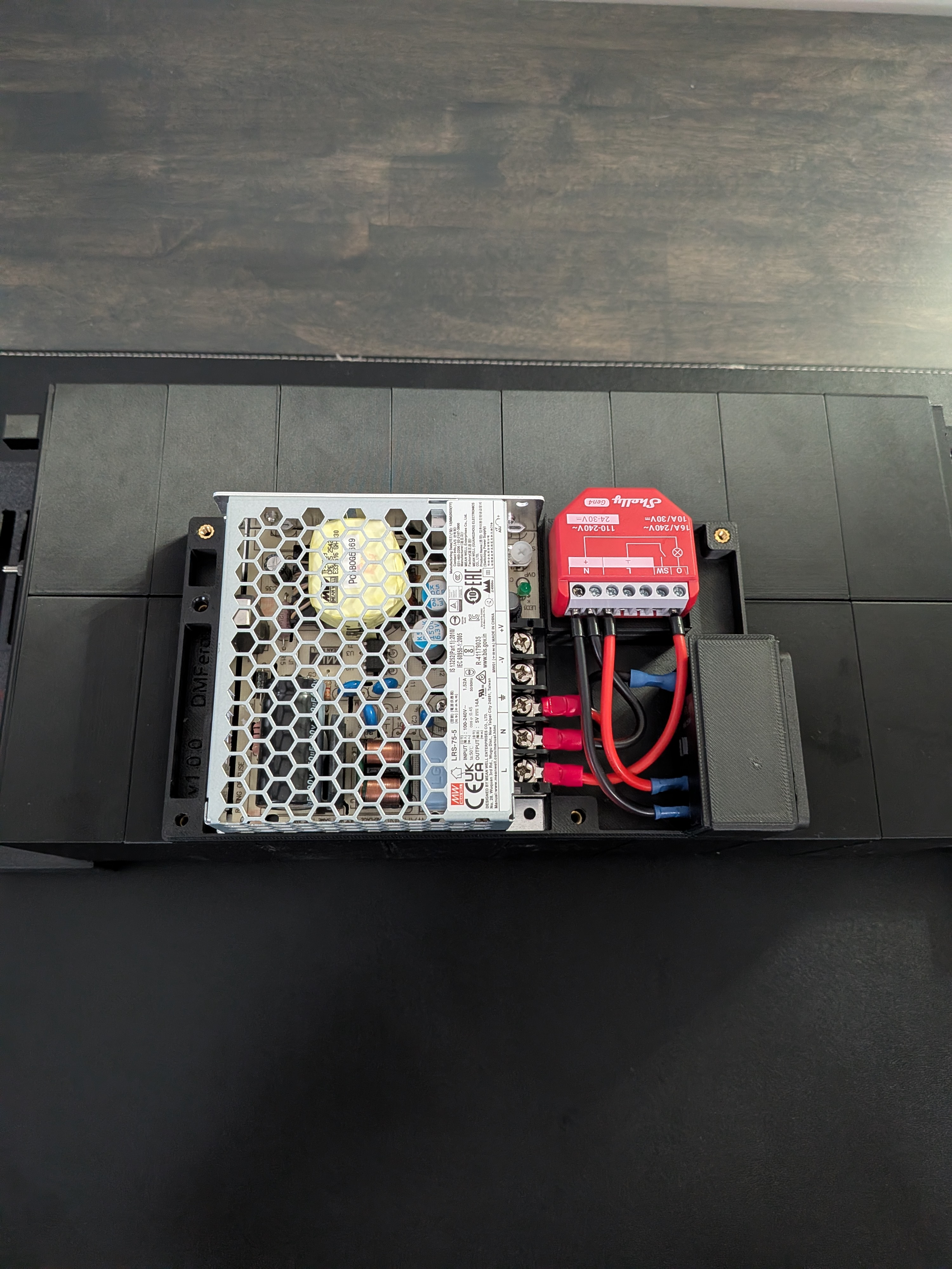
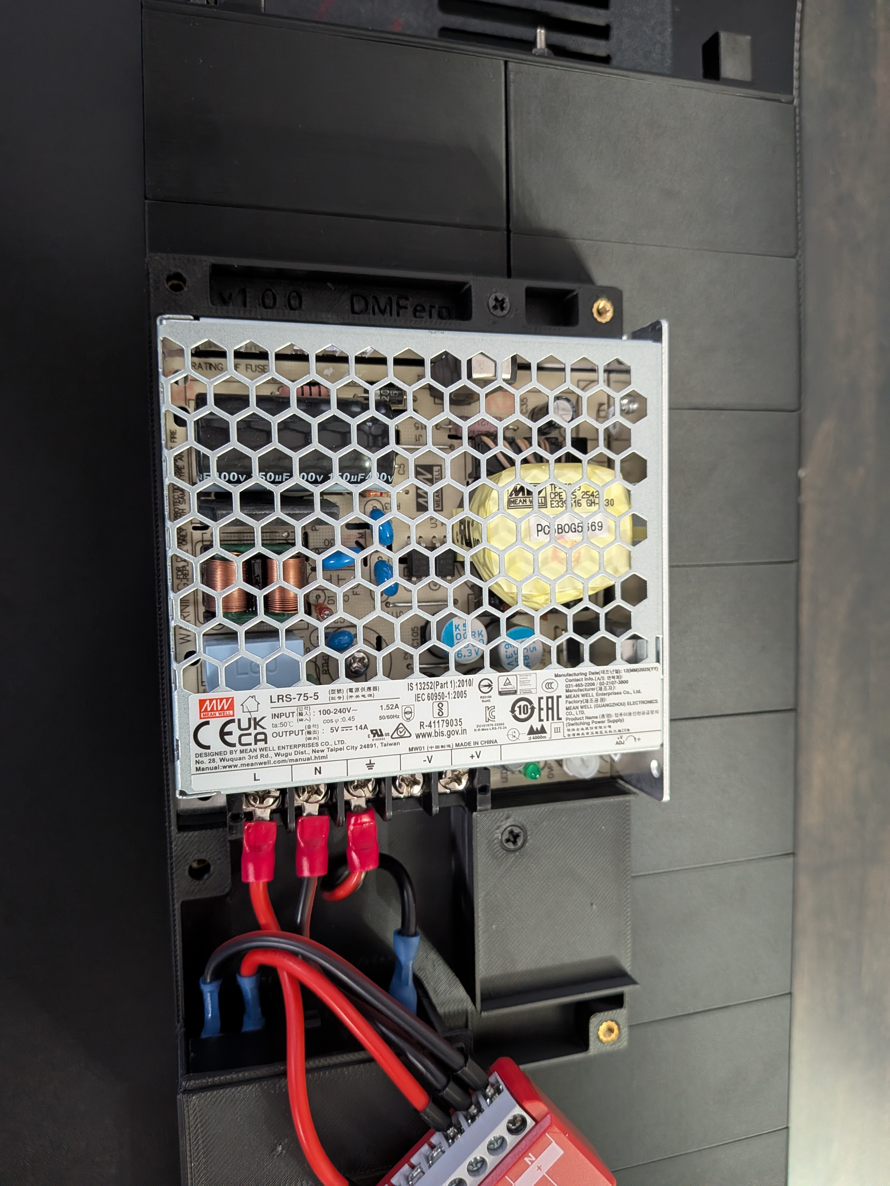
Screw down the 3 AC wires at the PSU terminals first, then connect the LINE and NEUTRAL wires to the outlet. Use the same outlet pins shown in the photo.
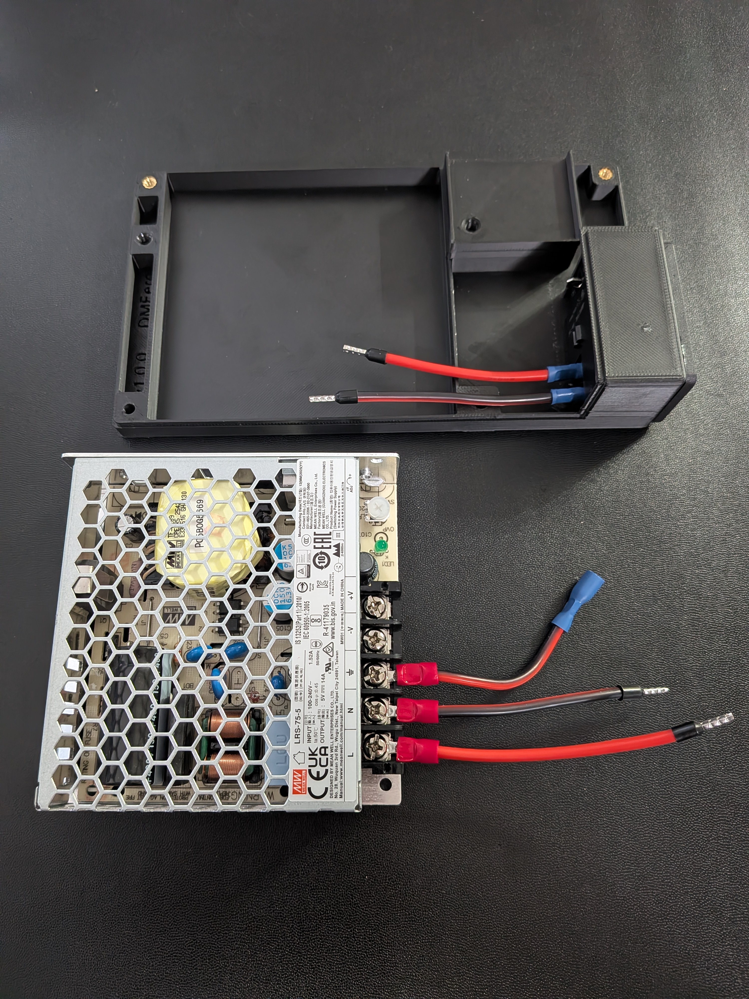
Next, place the LRS-75-5 into the enclosure and connect all the wires.
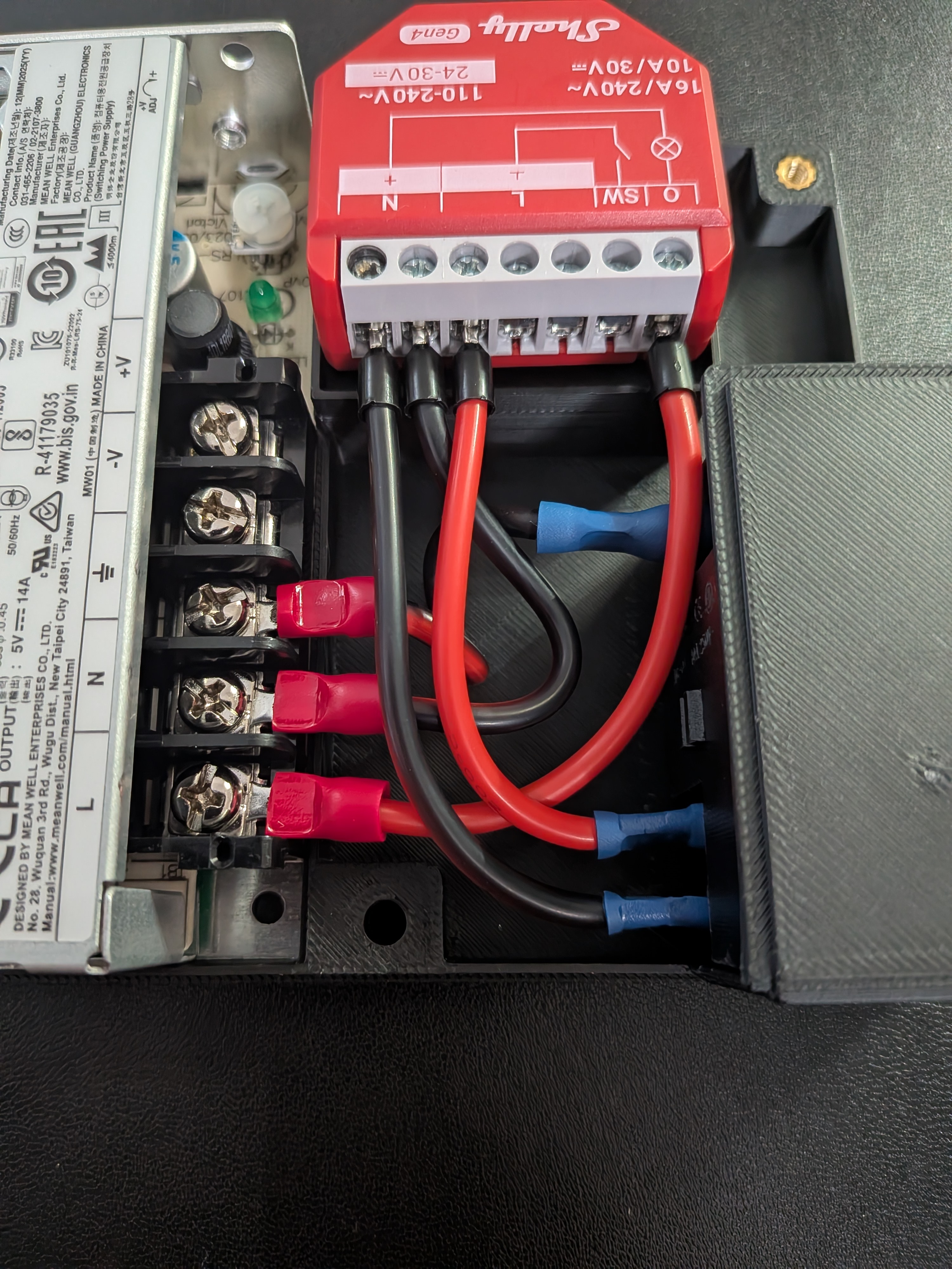
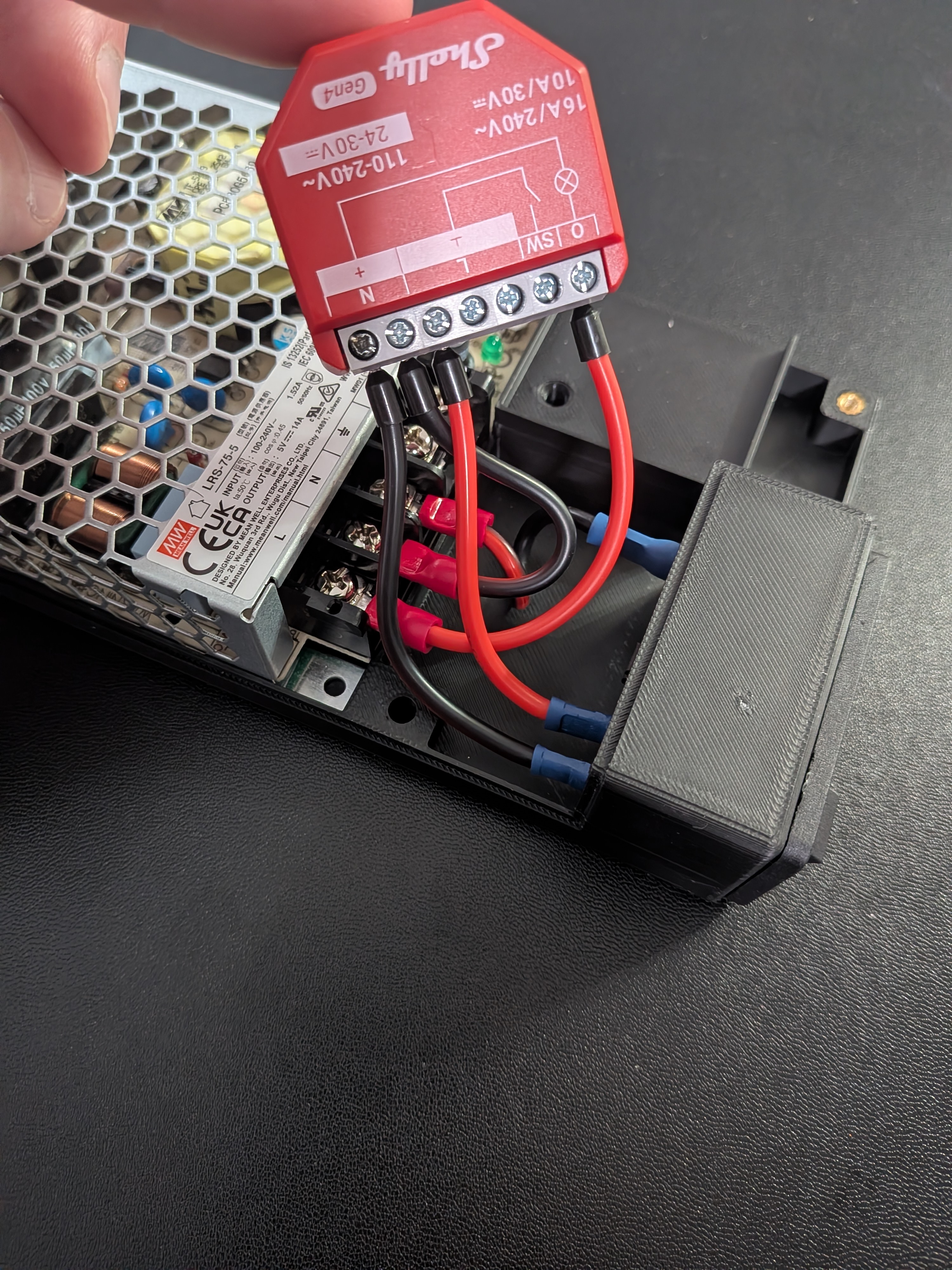
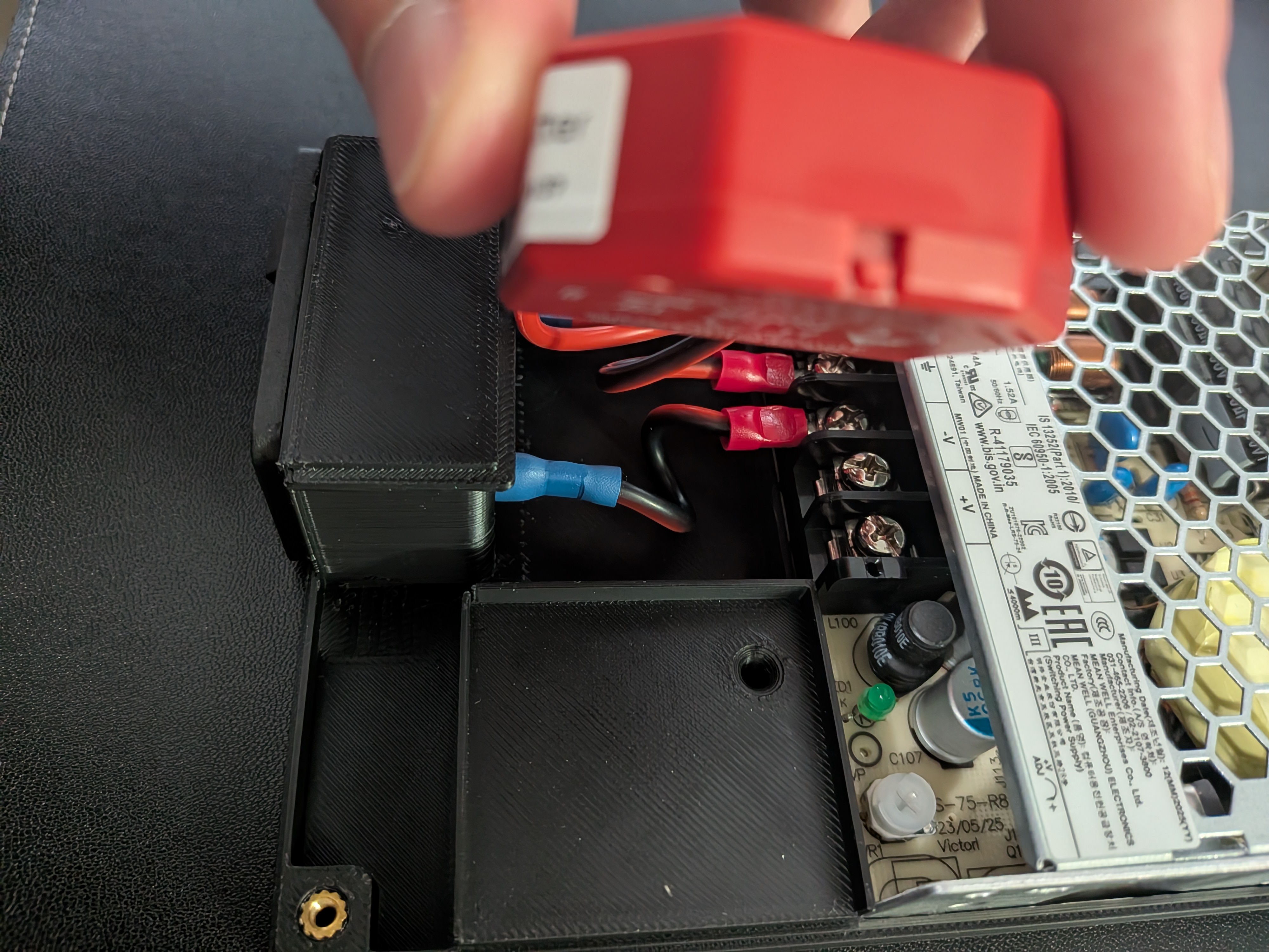
Screw down the 3 AC wires at the PSU terminals first, then connect all 3 to the outlet.
Tip
See the With Shelly tab for reference photos — the AC wiring at the PSU and outlet is similar.
A.12. Mount the PSU Enclosure
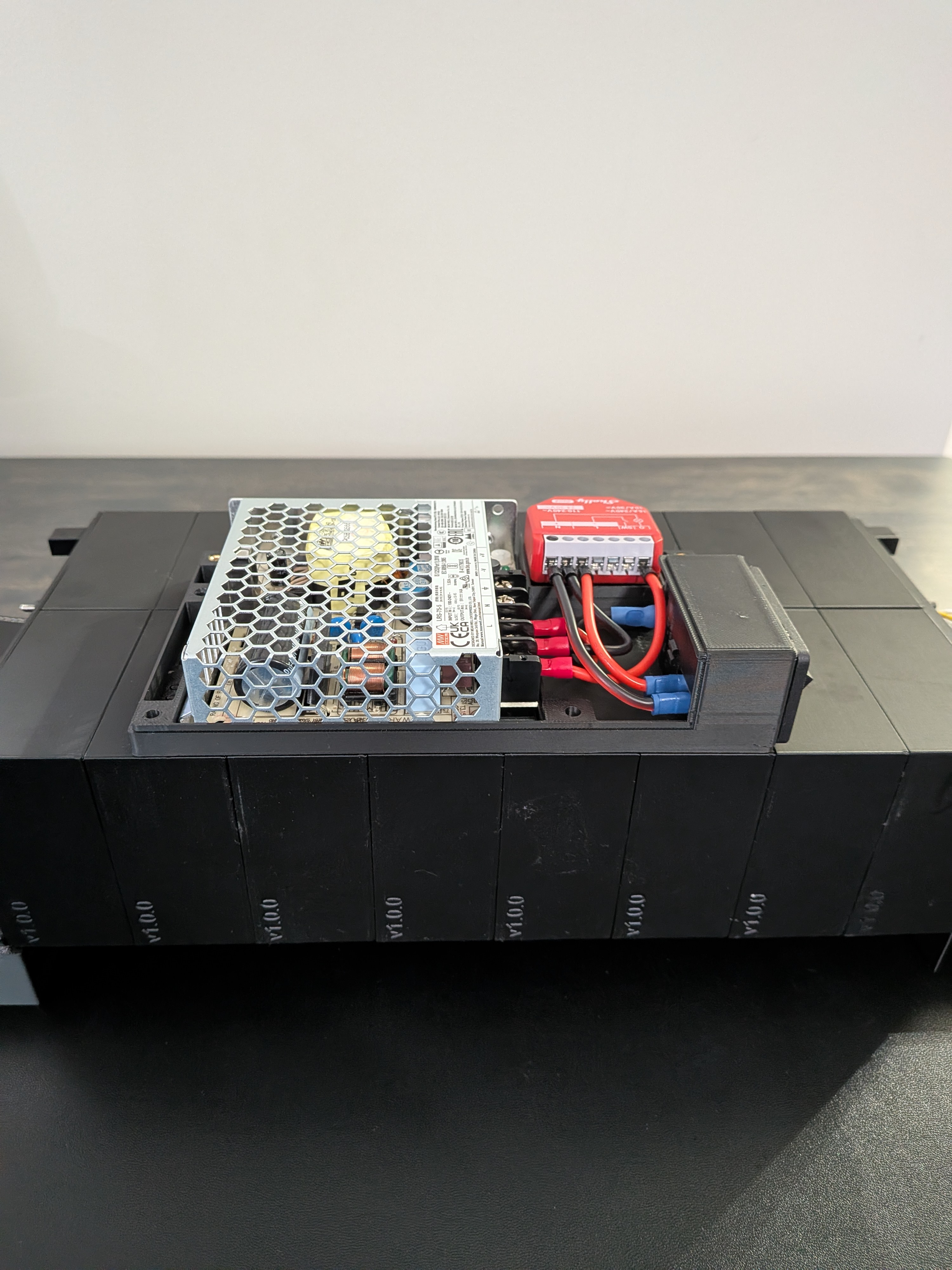
Place the PSU enclosure on the back of the display and secure it with M3 × 12mm screws through the two middle holes into the D.1 mounts. You'll need to push the Shelly aside to access the second screw.
A.13. Connect PSU to Controller Board
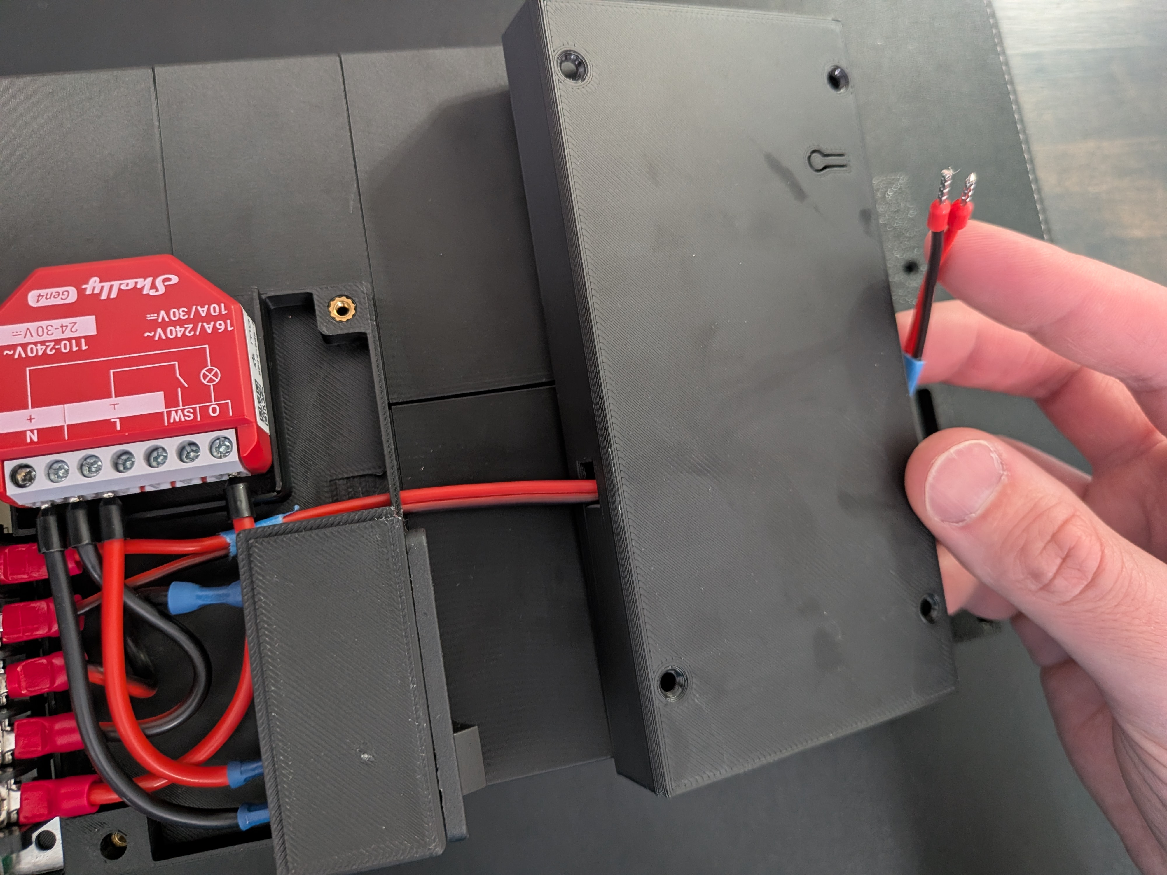
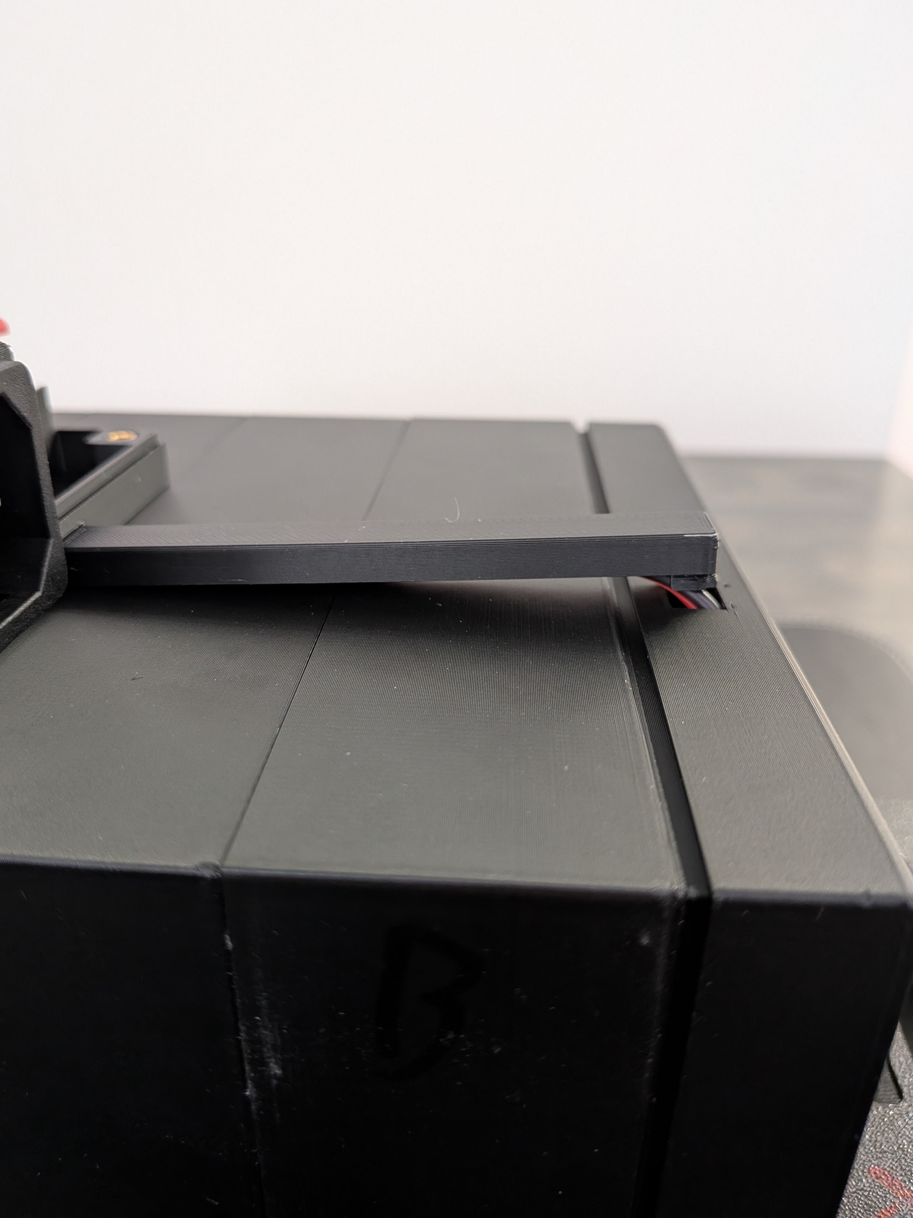
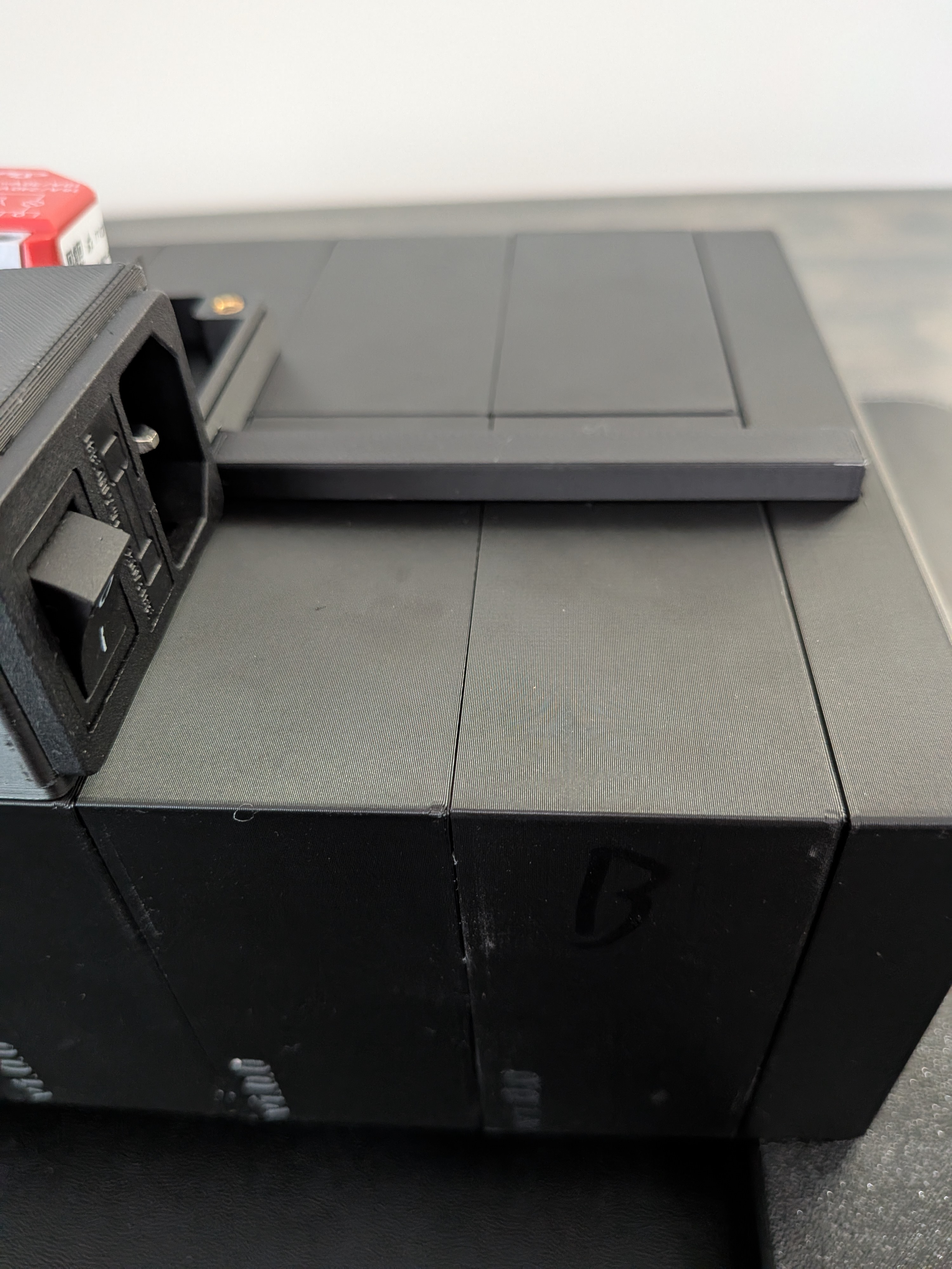
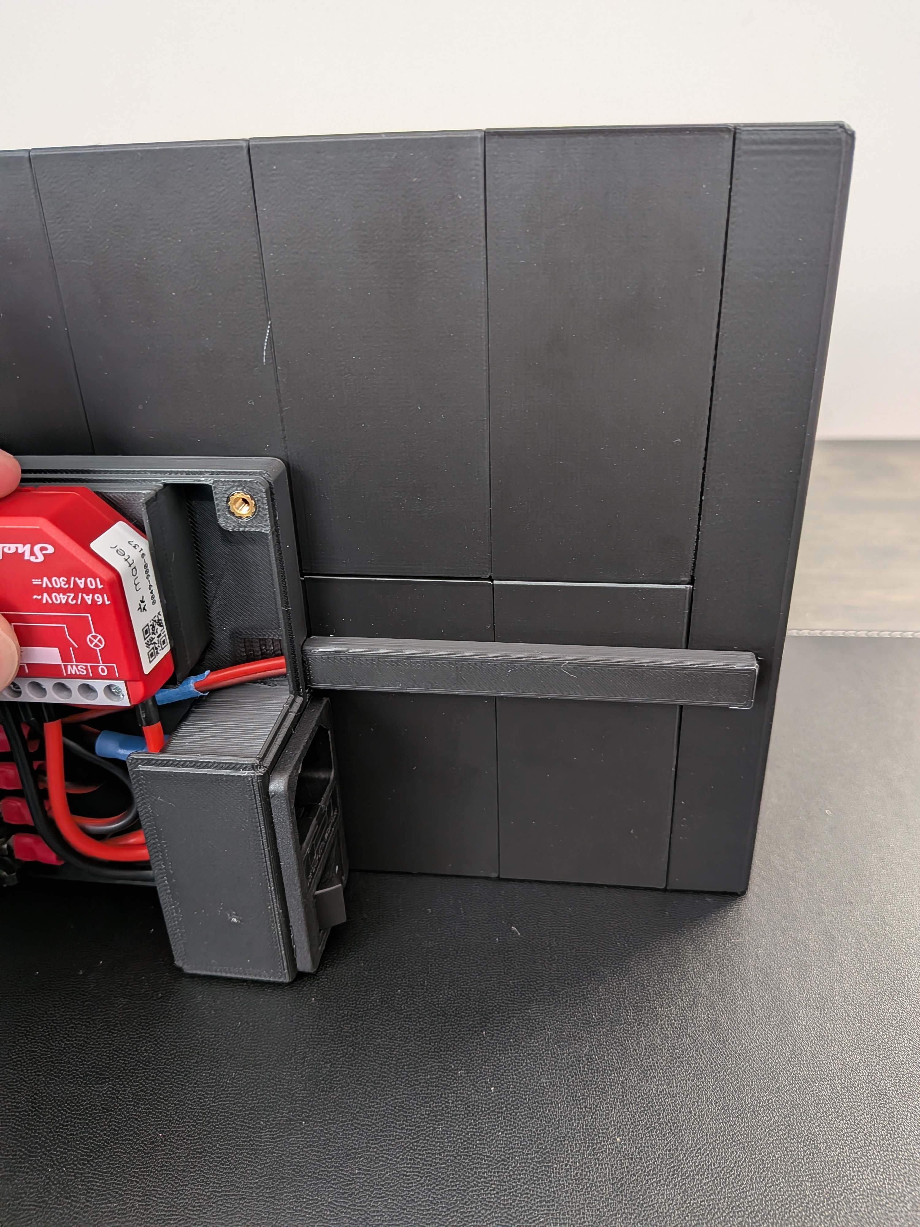
Thread the ferrule end of the 5V wires under the Shelly wires and out through the output hole on the PSU enclosure, just next to the outlet mount. Screw the ring end down at the PSU's +V and −V output terminals.
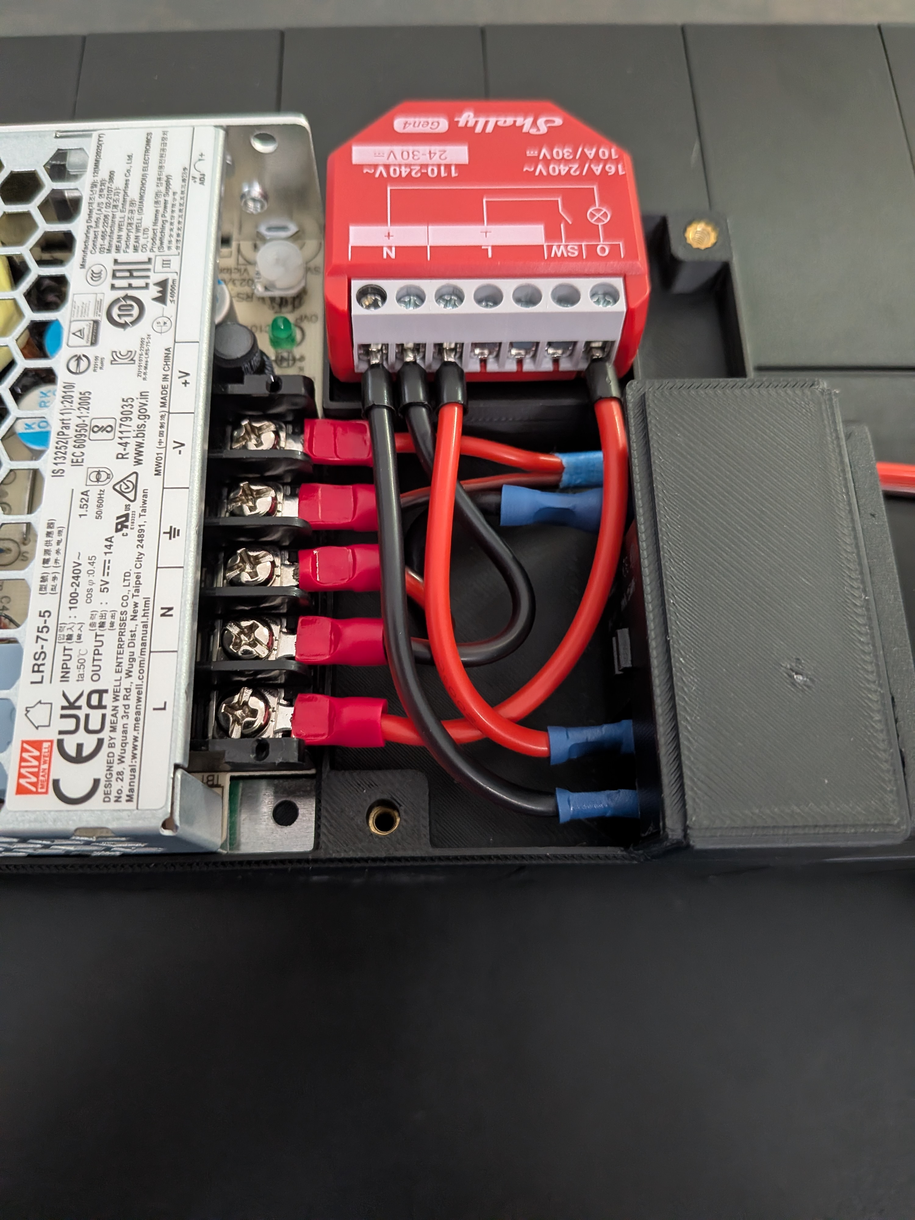
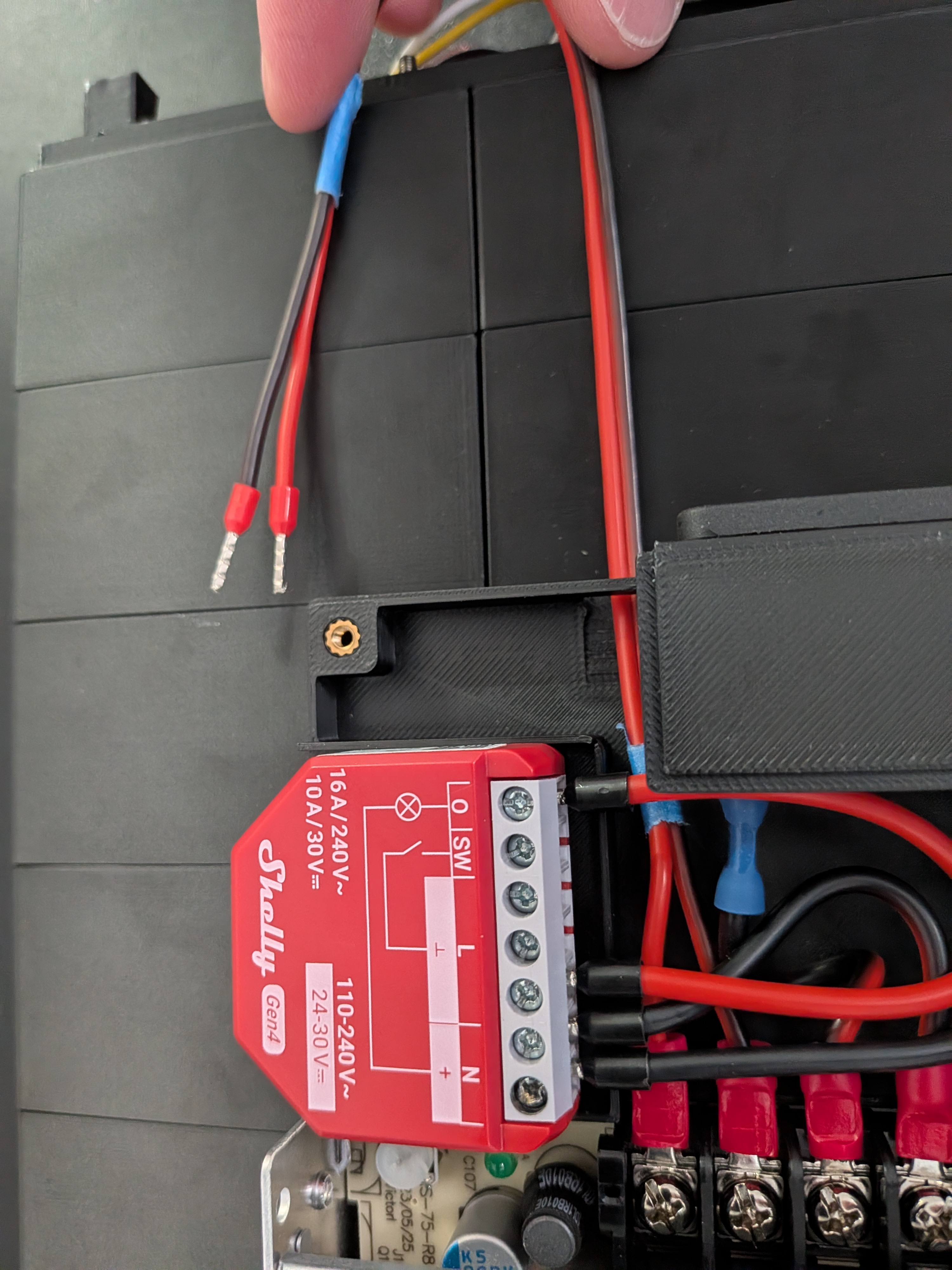
Thread the ferrule ends through the hole on the D.2 end cap. Don't attach the end cap to the end plate yet. Screw the two ferrule ends into the +5V and GND terminals on the controller board.
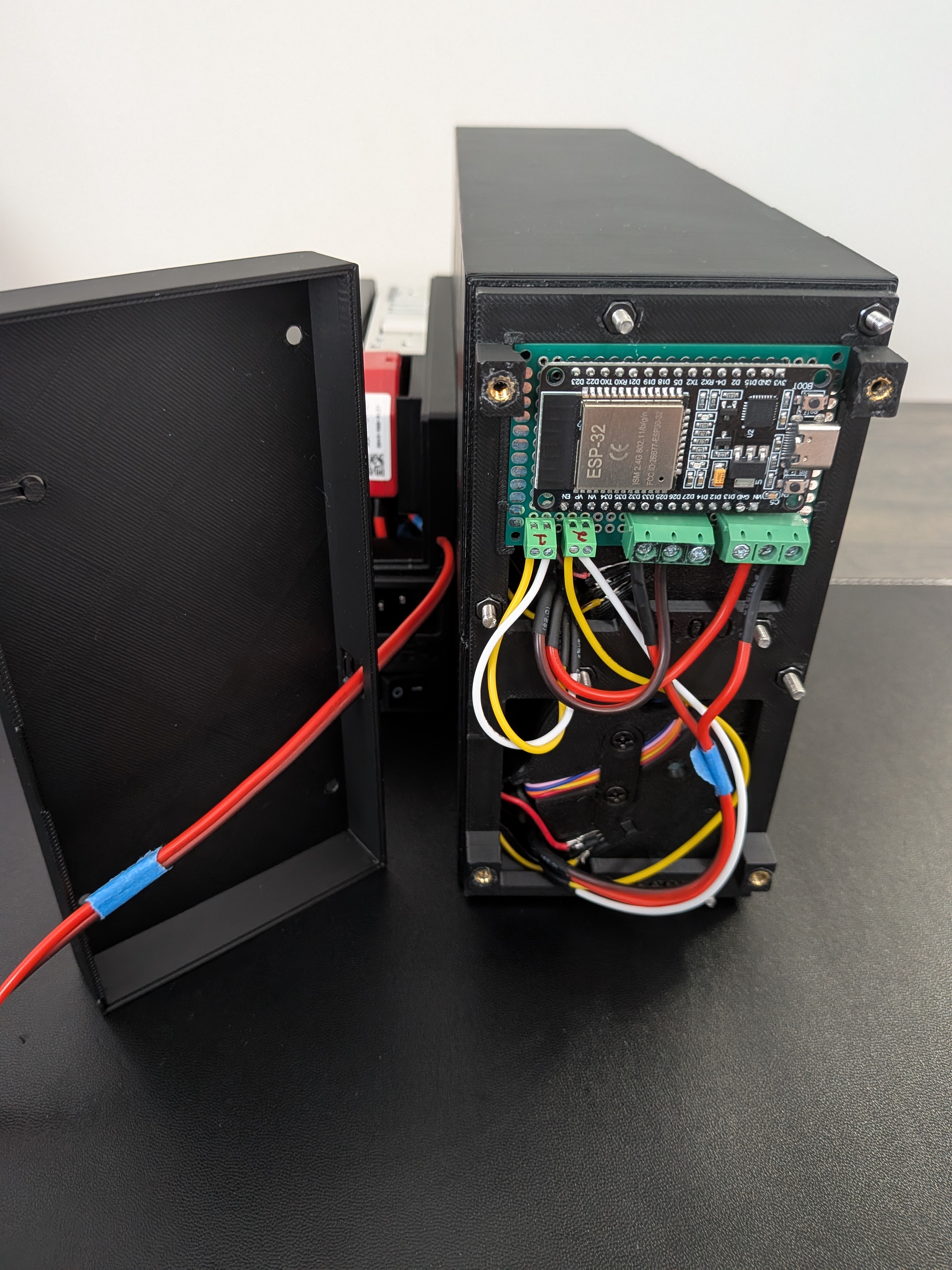
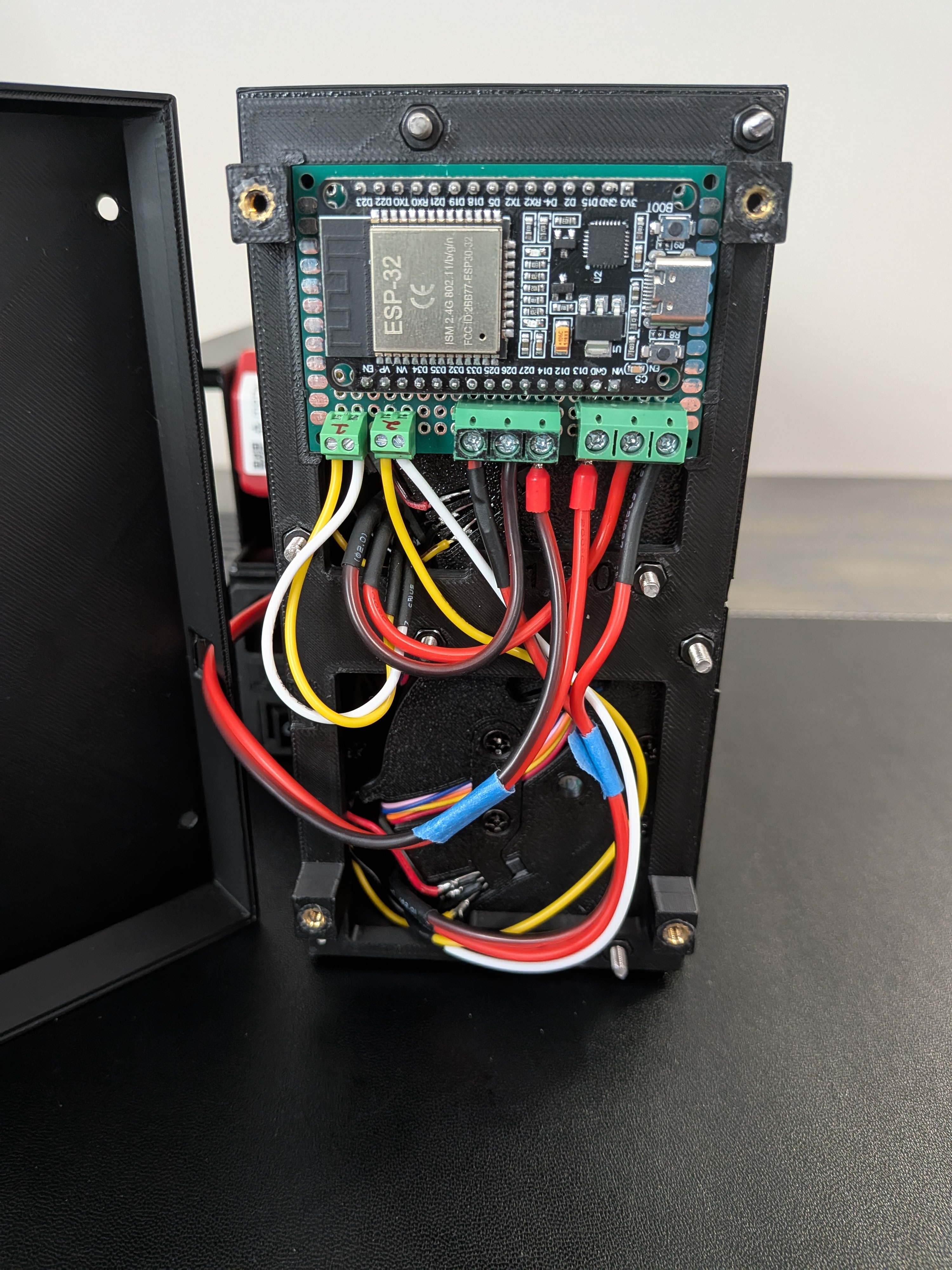
Warning
Double-check all wiring one last time before closing the end cap.
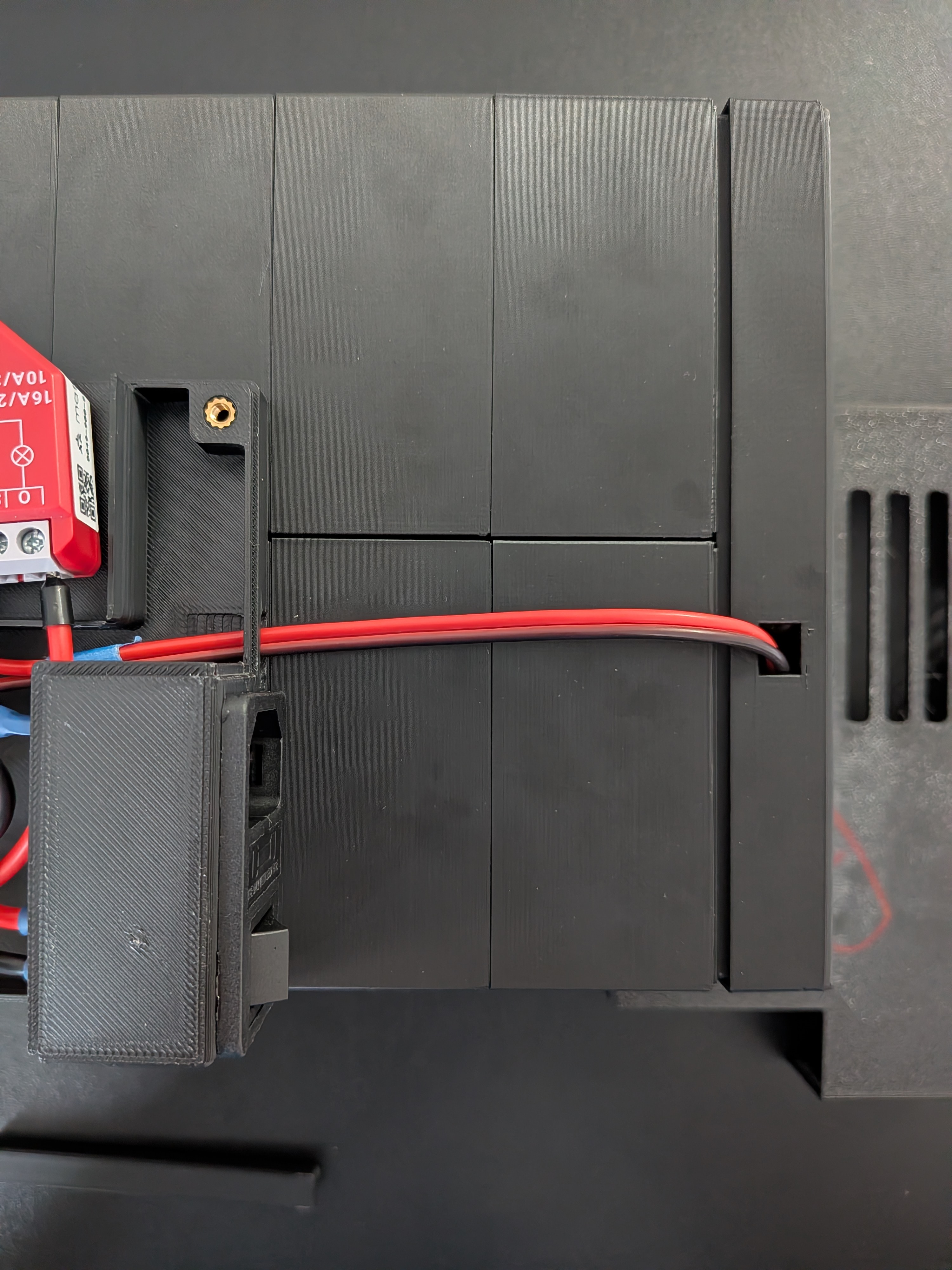
Position the end cap over the end plate, leaving a small gap. Place one end of the wire cover into the PSU enclosure (routing the 5V wires through it) and align the other end over the hole on the end cap. Push the end cap fully closed while simultaneously pressing the wire cover into the hole — done correctly, the wire cover will lock into place.
A.14. Close the Enclosure
Place the PSU enclosure top onto the mounted bottom half. Make sure the Shelly is seated in its slot, then press the top fully closed. Secure with 4 screws — M3 × 35mm for the bottom two holes and M3 × 30mm for the top two.
Warning
Double-check all wiring one last time before closing the enclosure top.
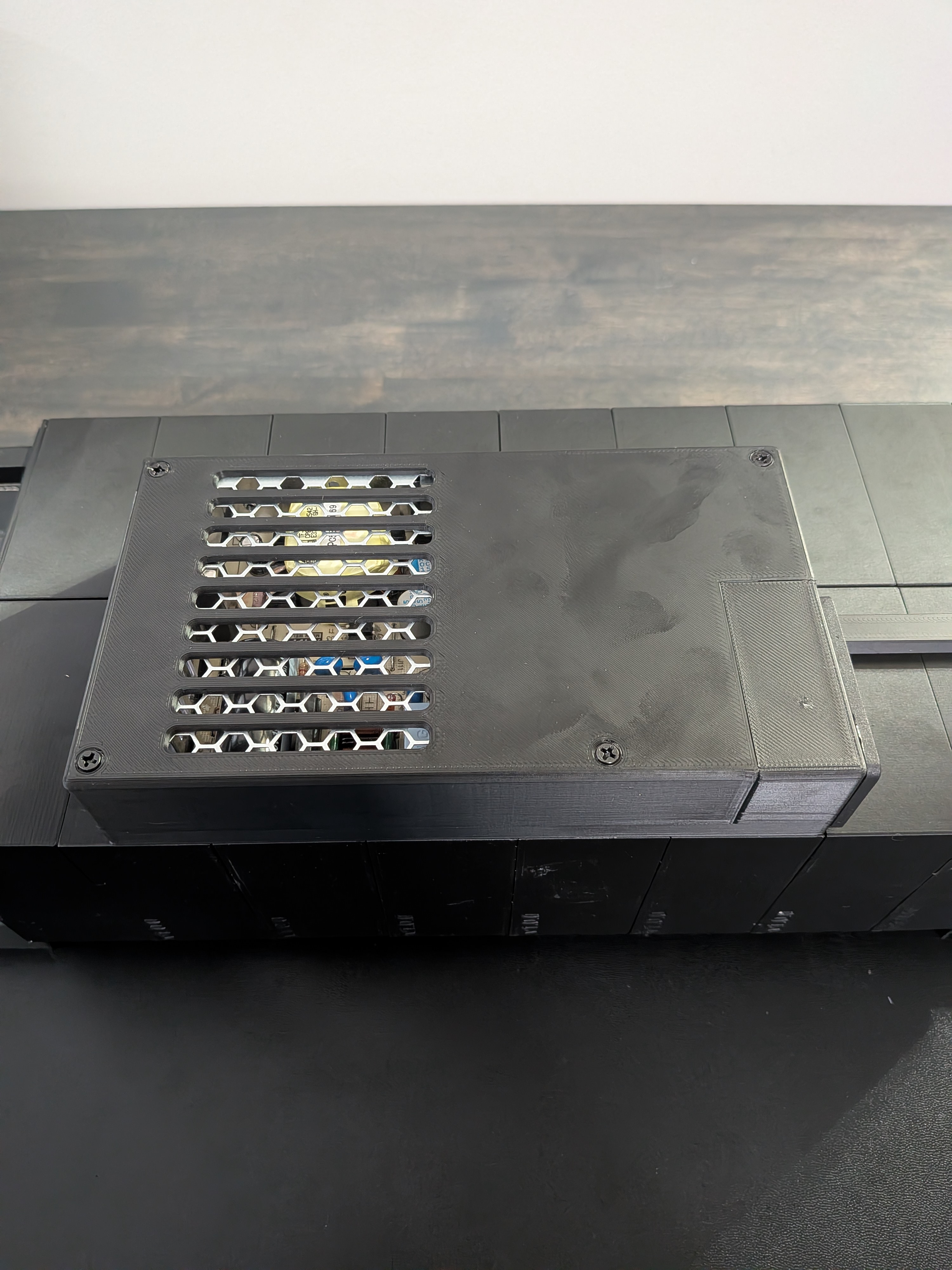
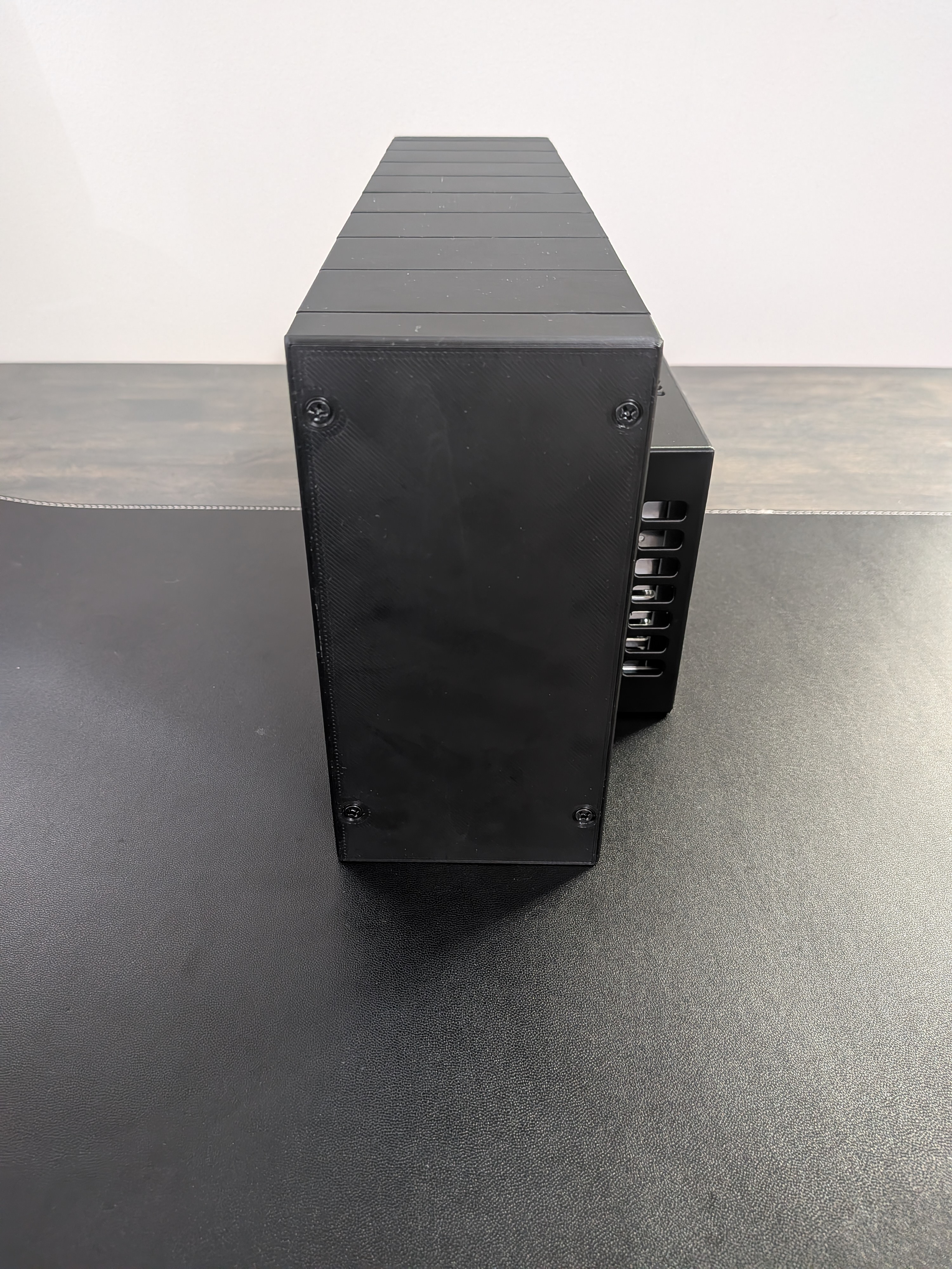
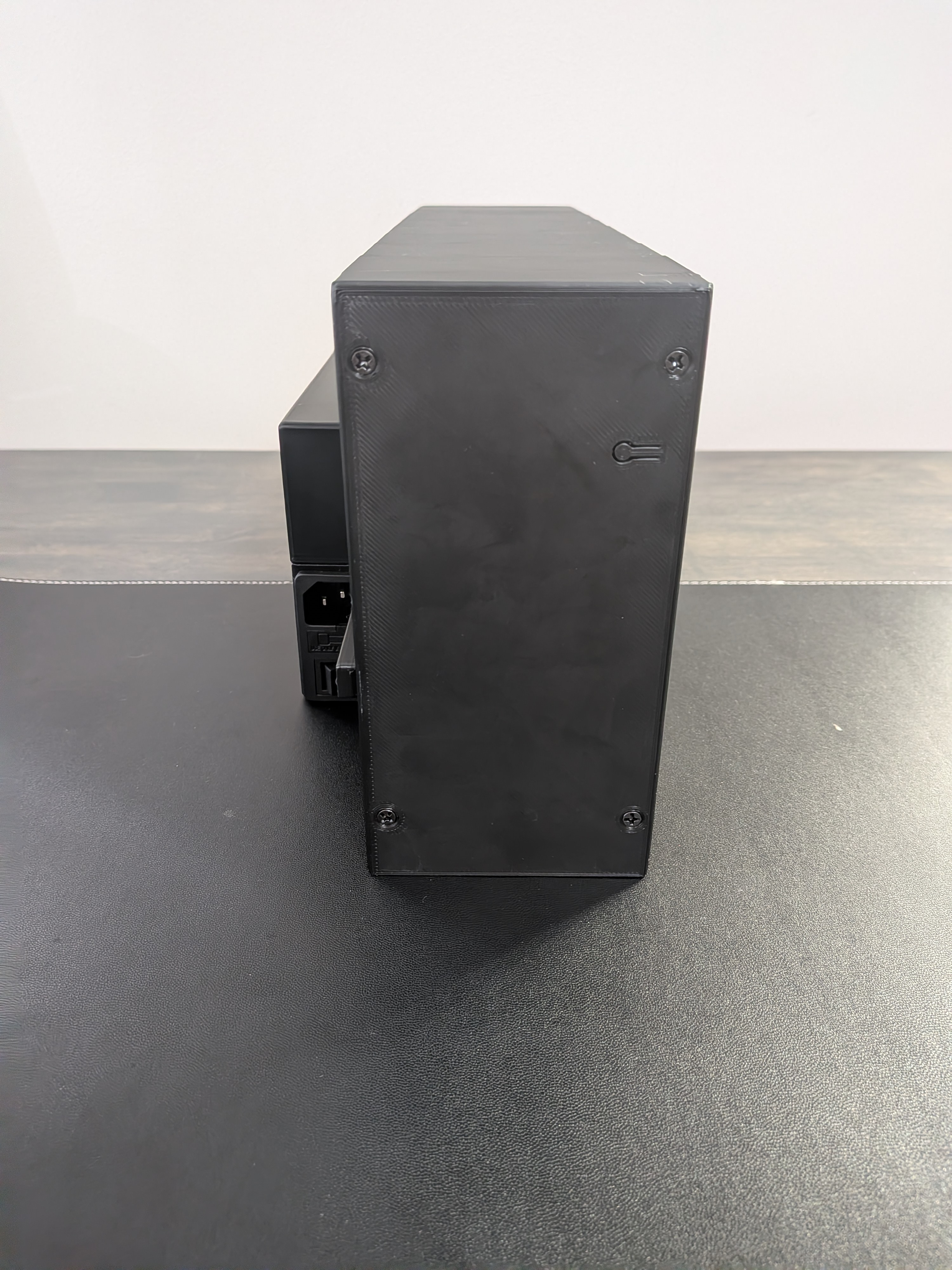
Confirm the 8 threaded rod nuts on the right end plate are hand-tight. Place the right end cap over the plate, then secure both end caps with 8 M3 × 6mm screws (4 on each side).
A.15. Power On & Test
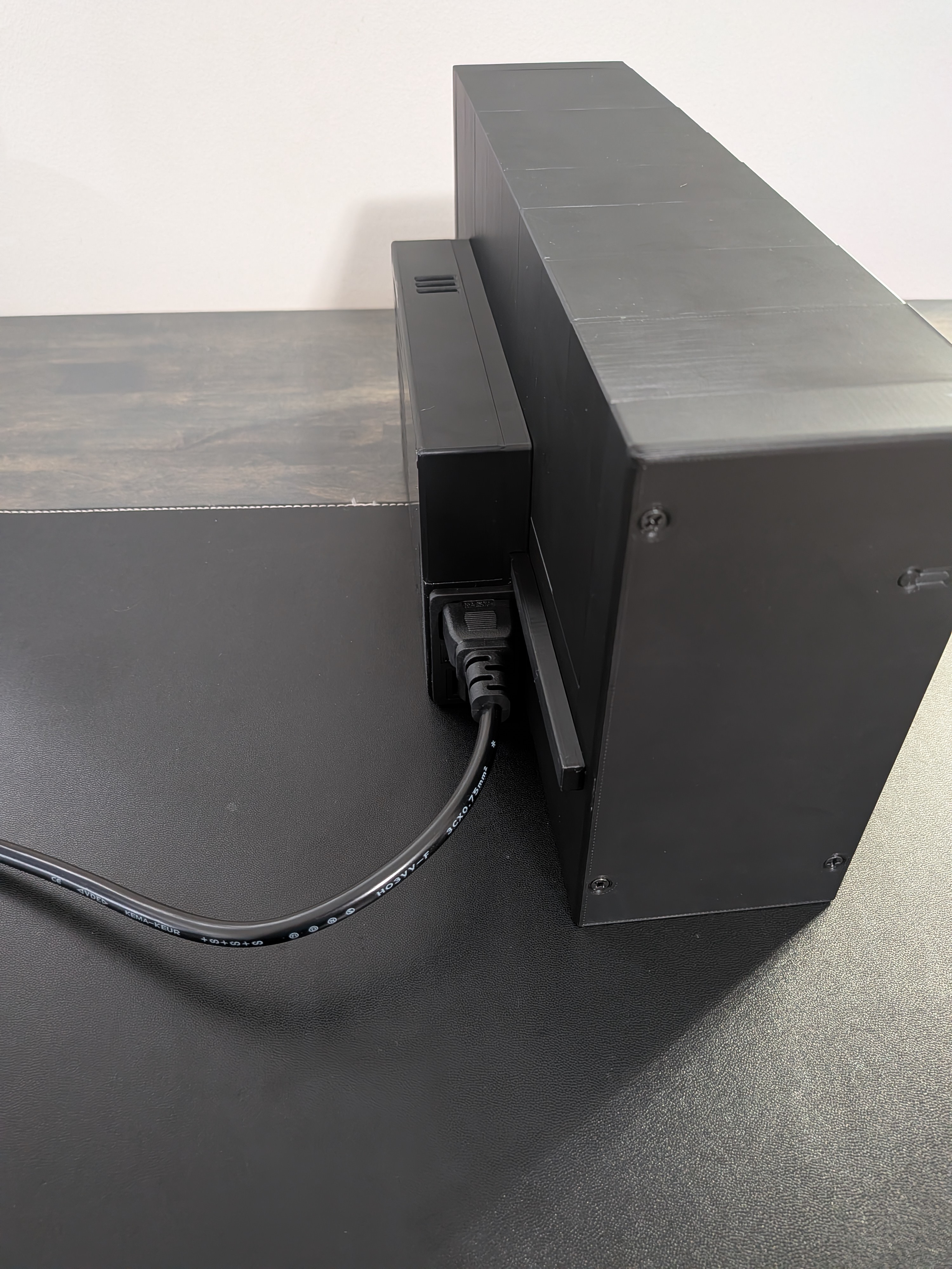
Plug in the power cord, flip the main switch, and verify the display boots and all modules respond.
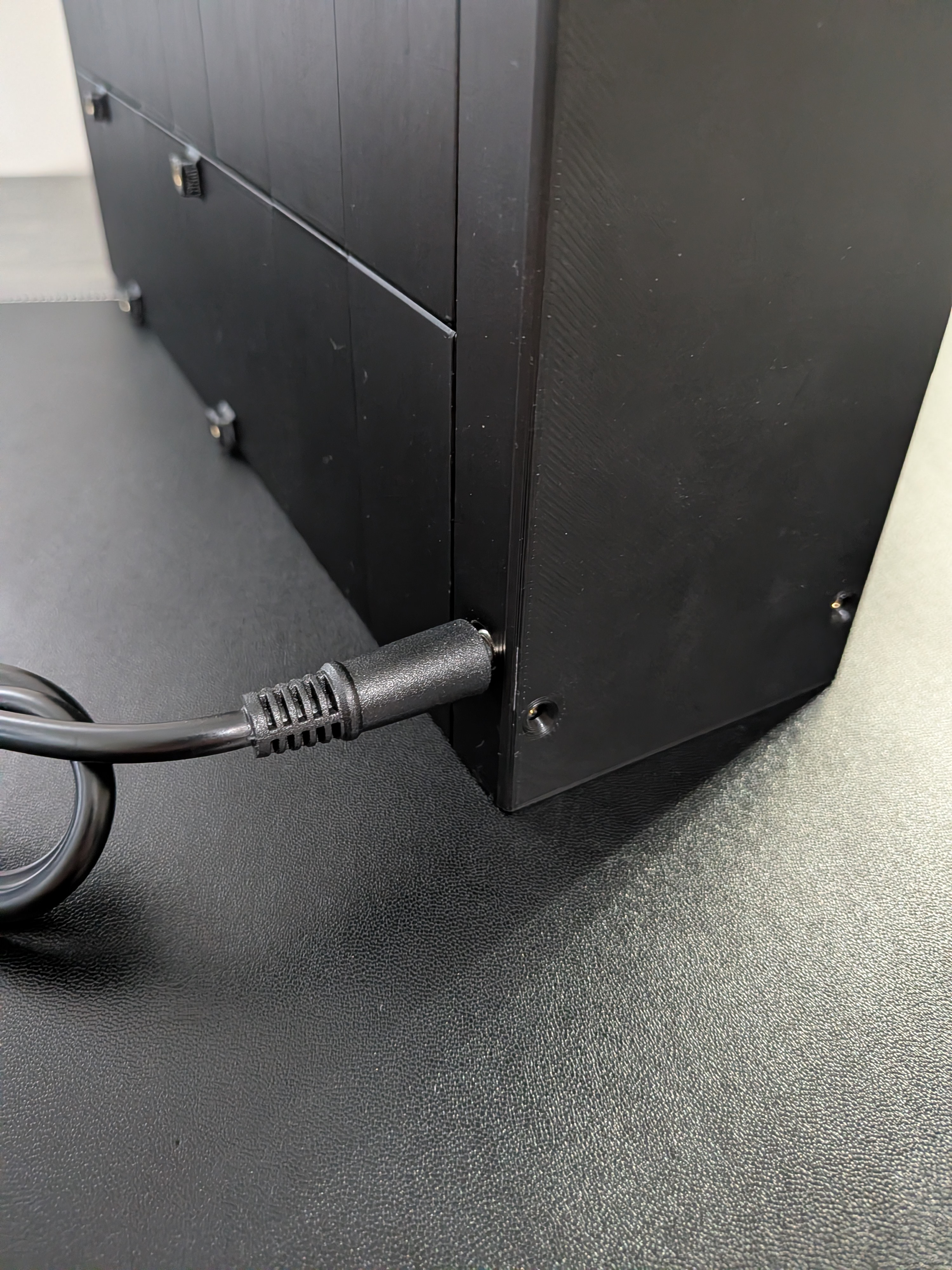
B.9. Install Barrel Jack
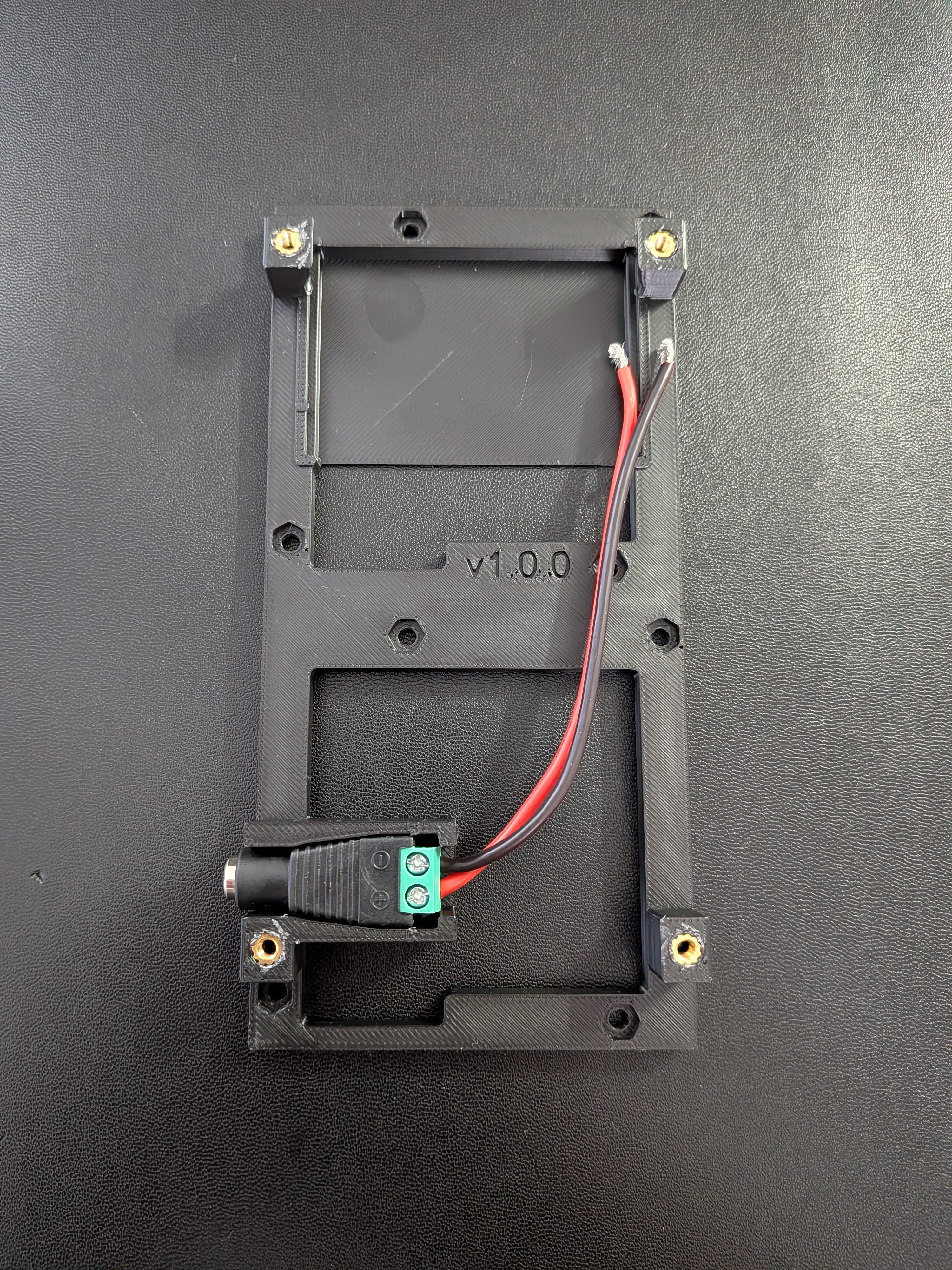
Cut the 5V and GND wires to approximately 100mm each. Connect one end of each wire to the controller board's 5V/GND input terminals, and the other end to the barrel jack. Seat the barrel jack into the cutout in the C.1 or C.2 left end cap (matched to your jack diameter).
B.10. Close the Enclosure
Confirm the 8 threaded rod nuts on the right end plate are hand-tight. Place both end caps over their plates and secure with 8 M3 × 6mm screws (4 on each side). Make sure the barrel jack remains seated in its cutout as you close the left end cap.
B.11. Power On & Test
Plug in the external 5V power supply and verify the display boots and all modules respond.